
Noise reduction air duct of axial flow fan

An axial flow fan and noise reduction technology, applied to axial flow pumps, components of pumping devices for elastic fluids, supporting machines, etc., can solve problems such as user discomfort, loud noise, affecting work efficiency and rest quality , to achieve the effect of noise elimination, to ensure the effect of noise reduction and noise reduction

Pending Publication Date: 2022-07-08
刘西保
View PDF0 Cites 0 Cited by
  • Summary
  • Abstract
  • Description
  • Claims
  • Application Information

AI Technical Summary

Problems solved by technology

[0006] The invention provides a noise-reducing air cylinder of an axial flow fan, one of which is to provide a porous fiber sound-absorbing layer, a vacuum sound-insulating layer, a built-in sound-absorbing cotton layer, and a noise-reducing sound-absorbing grid layer, so as to solve the problem of existing axial flow fans. During use, loud noises are often generated, which will bring physical discomfort to users and seriously affect their work efficiency and quality of rest.

Method used


Image

  • Noise reduction air duct of axial flow fan
  • Noise reduction air duct of axial flow fan
  • Noise reduction air duct of axial flow fan

Examples


Embodiment 1

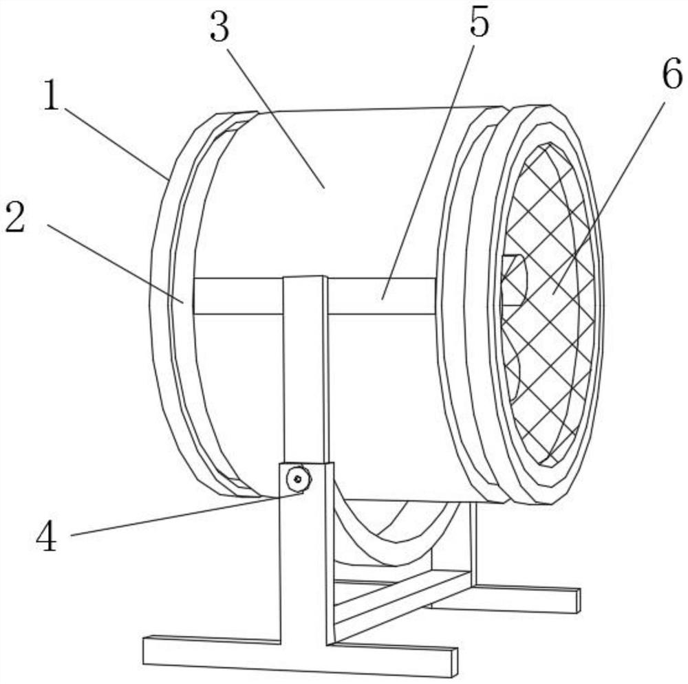
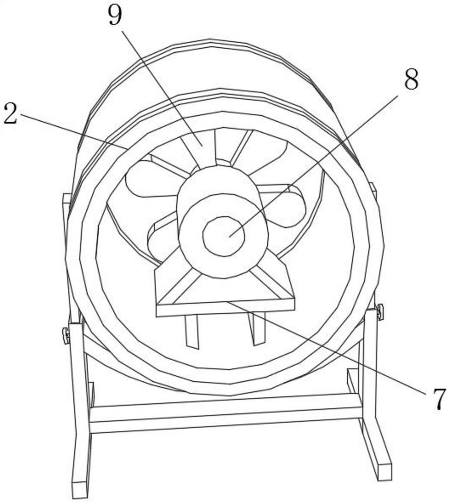
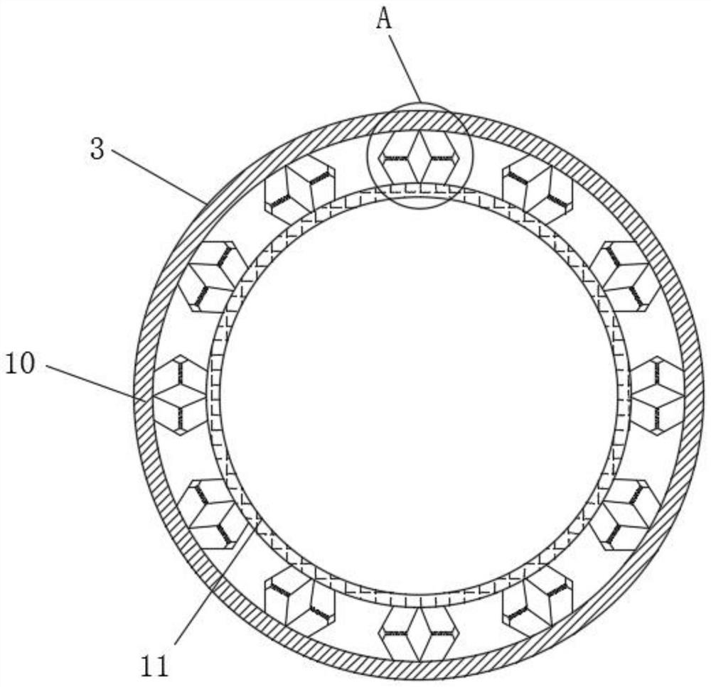
[0040] like Figure 1-7 As shown, the present invention provides a noise reduction air duct for an axial flow fan, comprising a main body device 1, an axial flow fan 2 is arranged inside the main body device 1, and an external protective sleeve 3 is arranged on the outer wall of the axial flow fan 2, A load-bearing adjustment bracket 4 is provided below the external protective sleeve 3, and the load-bearing adjustment bracket 4 is provided to play a supporting role and also to carry the vertical adjustment gear rod 25. The bearing carrier, the inside of the axial flow fan 2 is provided with auxiliary rubber The cushion layer 16 and the auxiliary rubber cushion layer 16 are provided to ensure the barrier protection between the external protective sleeve 3 and the axial flow fan 2, and the sound insulation cushion layer is protected to ensure its service life. The inner wall of the auxiliary rubber cushion layer 16 is fixedly connected There is a porous fiber sound-absorbing lay...

Embodiment 2

[0045] like Figure 1-7 As shown, on the basis of Embodiment 1, the present invention provides a technical solution: preferably, the upper surface of the load-bearing adjusting bracket 4 is provided with a vertical upward moving groove 26, and the vertical upward moving groove 26 is opened to facilitate vertical Towards the movement of the adjusting gear rod 25, the inner wall of the vertical upward moving through slot 26 is movably connected with the vertical adjusting gear rod 25. The function of the vertical adjusting gear rod 25 is to support the support rod of the axial flow fan 2, and the vertical adjusting gear rod The top side of the 25 is movably connected with a horizontal reinforcing plate 5. The installation of the horizontal reinforcing plate 5 is to ensure the firmness of the connection between the vertical adjustment gear rod 25 and the axial flow fan 2, and the horizontal reinforcing plate 5 is far away from the vertical adjustment gear rod 25. One side is fixe...


PUM


Abstract

The invention discloses a noise reduction air duct of an axial flow fan, and relates to the technical field of axial flow fans, the noise reduction air duct comprises a main body device, the axial flow fan is arranged in the main body device, an external protective sleeve is arranged on the outer wall of the axial flow fan, and a bearing adjusting support is arranged below the external protective sleeve; an auxiliary rubber cushion layer is arranged in the axial flow fan, a porous fiber silencing layer is fixedly connected to the inner wall of the auxiliary rubber cushion layer, and a vacuum sound insulation layer is arranged on the inner wall of the porous fiber silencing layer. Noise is eliminated and absorbed through the porous fiber noise reduction layer, the vacuum sound insulation layer, the built-in sound absorption cotton layer and the noise reduction and sound absorption grid layer, and the problem that the working efficiency and rest quality of a user are seriously affected by noise generated in the using process of an existing axial flow fan is solved. And the transmitted noise vibration is captured through the interior of the noise reduction and sound absorption grid layer, so that the noise reduction and sound attenuation effects during operation of the axial flow fan are further ensured.

Description

technical field [0001] The invention relates to the technical field of axial flow fans, in particular to a noise reduction air duct of an axial flow fan. Background technique [0002] Axial flow fans are very widely used, that is, the airflow in the same direction as the axis of the fan blades, such as electric fans, air conditioner outdoor fans are axial flow fans. It is called "axial flow" because the gas flows parallel to the fan axis. Axial flow fans are usually used in applications with high flow requirements and low pressure requirements. Axial fans fix the position and move the air. The axial flow fan is mainly composed of the fan impeller and the casing. The structure is simple but the data requirements are very high. When the impeller rotates, the gas enters the impeller axially from the air inlet, and is pushed by the blades on the impeller to increase the energy of the gas, and then into the guide vane. The guide vanes turn the deflected airflow into an axial ...

Claims


Application Information

Patent Timeline
IPC IPC(8): F04D19/00F04D29/66F04D29/52F04D29/70F04D29/00F16M11/04F16M11/20B32B1/08B32B33/00B32B3/12B32B5/02B32B25/10
CPCF04D19/002F04D29/663F04D29/664F04D29/668F04D29/522F04D29/703F04D29/002F16M11/046F16M11/04F16M11/20B32B1/08B32B33/00B32B3/12B32B5/02B32B25/10B32B2307/102B32B2307/10
Inventor 刘西保
Owner 刘西保
Learn More