
Automatic shell withdrawing device for stretching forming of battery steel shell

A technology of stretch forming and battery steel shell, which is applied in the direction of forming tools, final product manufacturing, manufacturing tools, etc. It can solve the problems that affect the ejection of the return spring, there is no lubrication device in the forming hole, and affect the shell ejection process, so as to improve the processing efficiency. , the effect is good, the effect of reducing friction

Active Publication Date: 2022-07-08
新乡市正元电子材料有限公司
View PDF14 Cites 0 Cited by
  • Summary
  • Abstract
  • Description
  • Claims
  • Application Information

AI Technical Summary

Problems solved by technology

[0005] 1. There is no lubricating device for the sliding part of the forming hole and the ejector post. If the lubrication is not timely, the friction between the ejector post and the forming hole will increase. If the friction between the ejector post and the forming hole increases, it will affect the ejection of the return spring to the ejector post.
[0006] 2. The installation block and the surface of the forming hole steel case also need to be lubricated. If the forming hole is not lubricated before the battery steel case is formed, the skin of the formed battery steel case will be scratched and will be clamped into the forming hole, which will affect Shelling process

Method used


Image

  • Automatic shell withdrawing device for stretching forming of battery steel shell
  • Automatic shell withdrawing device for stretching forming of battery steel shell
  • Automatic shell withdrawing device for stretching forming of battery steel shell

Examples


Embodiment 1

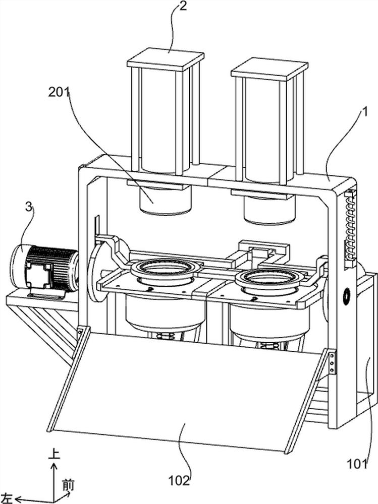
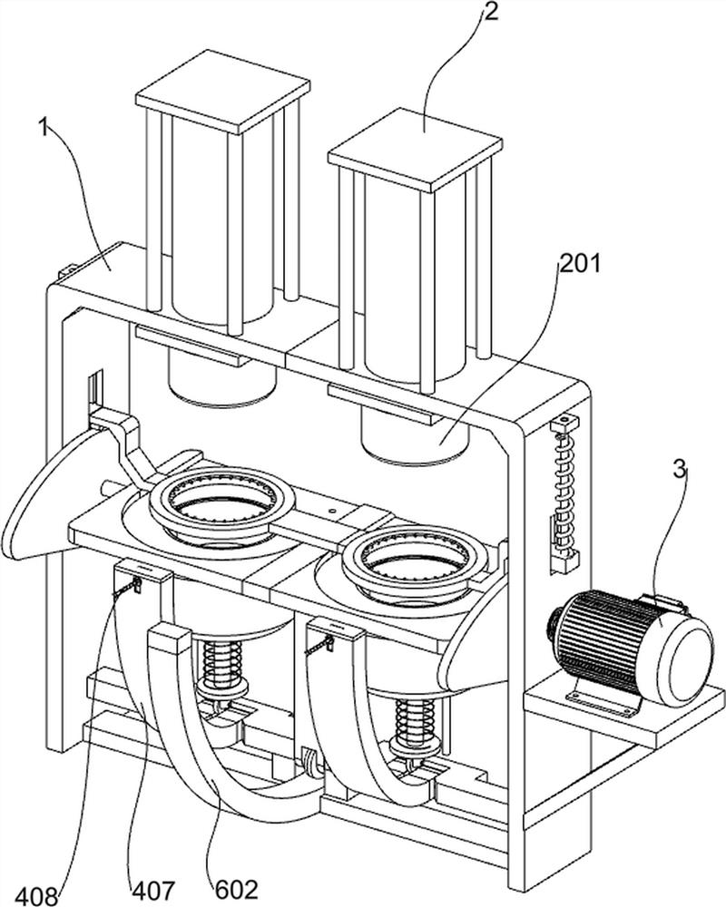
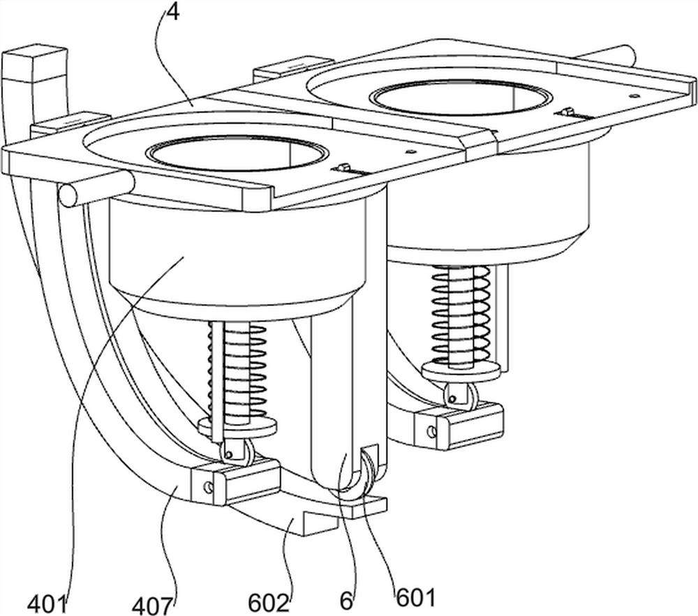
[0036] A battery steel shell stretching forming automatic shell removal device, such as Figure 1-4 As shown, it includes a support frame 1, a back plate 101, a swash plate 102, a cylinder 2, an upper stamping die 201, a motor 3, a stamping plate 4, a lower die 401, a push block 402, a sliding rod 403 and an unpacking assembly, the support frame 1. A back plate 101 is fixedly connected to the rear side, a sloping plate 102 is fixedly connected to the front side of the support frame 1, a cylinder 2 is installed on the upper side of the support frame 1, and an upper stamping die 201 is fixedly connected to the protruding end of the cylinder 2, and the support frame 1 rotates inside A stamping plate 4 is connected, a motor 3 is installed on the left side of the support frame 1, the output shaft of the motor 3 is fixedly connected with the stamping plate 4, the stamping plate 4 is fixedly connected with a lower die 401, and the lower die 401 is provided with a shell-removing compon...


PUM


Abstract

The invention relates to the field of battery production, in particular to an automatic shell withdrawing device for stretching forming of a battery steel shell. Comprising a supporting frame, a back plate, an inclined plate, an air cylinder, an upper stamping die, a motor, a stamping plate and the like. A back plate is fixedly connected to the rear side of the supporting frame, an inclined plate is fixedly connected to the front side of the supporting frame, an air cylinder is installed on the upper side of the supporting frame, the extending end of the air cylinder is fixedly connected with an upper stamping die, a stamping plate is rotationally connected into the supporting frame, a motor is installed on the left side of the supporting frame, and an output shaft of the motor is fixedly connected with the stamping plate. The upper stamping die and the lower die are matched to rapidly form materials, and when the driving mechanism drives the lower die to turn over by 90 degrees, the sliding rod drives the pushing block in the lower die to move towards the outer side to push out a stamped and formed steel shell.

Description

technical field [0001] The invention relates to the field of battery production, in particular to a battery steel shell drawing and forming automatic shell removal device. Background technique [0002] Authorization Bulletin No. CN 215746039U provides a cylindrical lithium battery steel shell stretching forming automatic shell removal device, including a shell, the top outer wall of the shell is connected with a mounting block by bolts, and the interior of the mounting block is provided with a forming hole, the forming hole is used for For the forming of the battery steel shell, a top column is movably inserted inside the forming hole, and the battery steel shell inside the forming hole is pushed out by the top column. The outer wall of one side of the horizontal plate is welded with a vertical plate, and the outer wall of one side of the vertical plate is welded with a guide sleeve. A cylinder is connected by bolts. The model of the cylinder is MA20X40. One end of the outp...

Claims


Application Information

Patent Timeline
Patent Type & Authority Applications(China)
IPC IPC(8): B21D22/20B21D37/14B21D45/04B21D37/18
CPCB21D22/20B21D37/142B21D45/04B21D37/18Y02P70/50
Inventor 梁平田鹏王需耀
Owner 新乡市正元电子材料有限公司
Learn More