Furniture equipment based on Internet of Things
A technology of the Internet of Things and furniture, applied in physical therapy, kneading massage appliances, instruments, etc., can solve the problems of single function of massage chairs and cannot meet the diverse massage needs of users, and achieve better results
- Summary
- Abstract
- Description
- Claims
- Application Information
AI Technical Summary
Problems solved by technology
Method used
Image
Examples
Embodiment 1
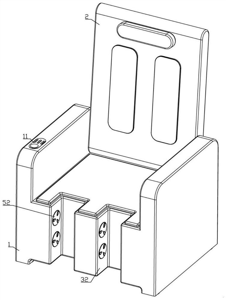
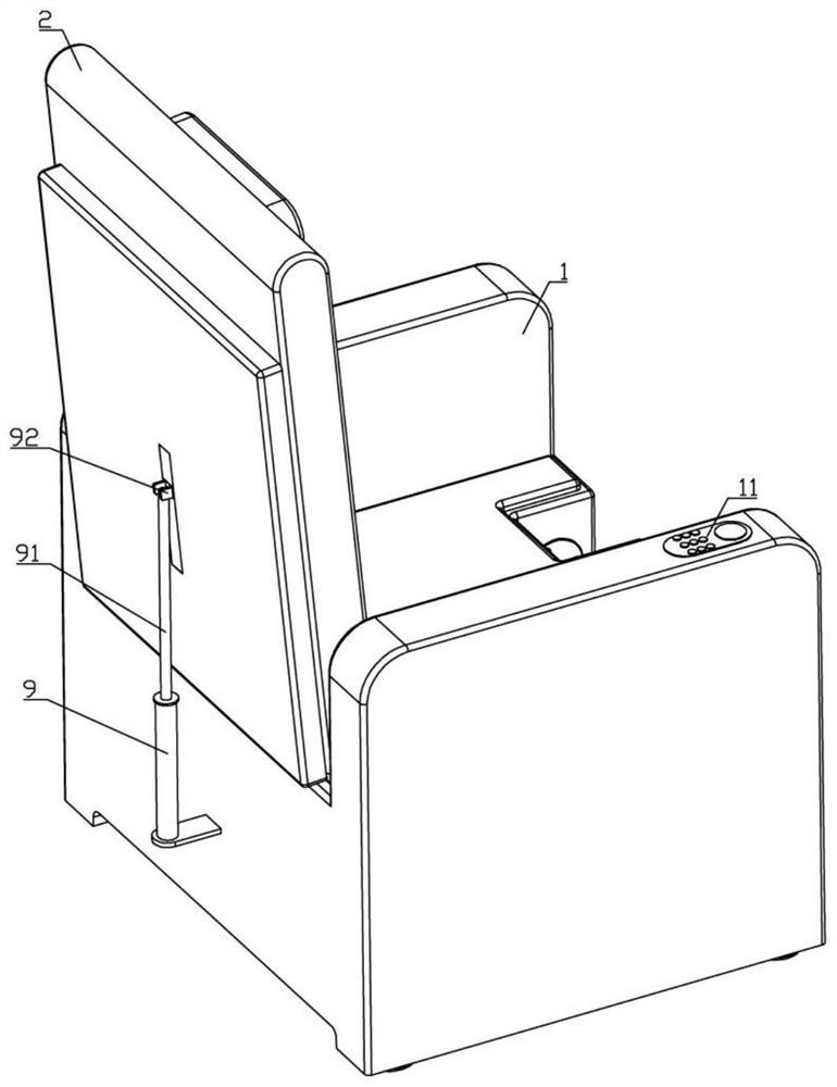
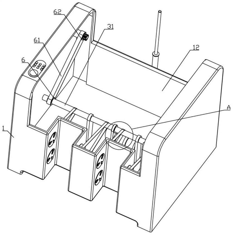
[0033] like Figure 1-5 , Figure 7-8 As shown, an IoT furniture device of the present invention includes a base 1 and a control panel 11. The base 1 is provided with a mounting cavity 12 and a first massage mechanism is provided inside. It is hollow and has a second massage mechanism inside, and a support mechanism is arranged on the rear side of the backrest 2;
[0034] The first massage mechanism includes a motor 3, a main shaft 31, two sets of leg massage assemblies and two chain drive assemblies. The main shaft 31 is rotatably arranged in the installation cavity 12, the motor 3 is connected to the main shaft 31 by transmission, and the front end of the base 1 is symmetrically provided with two The U-shaped cavity 32, the two leg massage components are connected to the main shaft 31 in a driving manner and are respectively matched with the two U-shaped concave holes 32, and the two chain transmission components are respectively arranged on both sides of the main shaft 31 ...
Embodiment 2
[0046] like Image 6 As shown, it is further improved on the basis of the first embodiment, a switch is provided between the driven shaft 4 and the second driven sprocket, and the switch includes the first electric telescopic rod 7, the transmission spline 71 and the spline Sleeve 72, the first electric telescopic rod 7 is embedded inside the second transmission sprocket 6 and is fixedly connected with the inner wall of the installation cavity 12, and the second driven sprocket is provided with a spline through groove 73 that matches the transmission spline 71 , the transmission spline 71 is slidably arranged in the spline through groove 73 and is fixedly connected with the output shaft of the first electric telescopic rod 7 , and the spline sleeve 72 is connected with the driven shaft 4 and matched with the transmission spline 71 .
[0047] In order to avoid the movement of the first massage mechanism and the second massage mechanism due to the rotational force when adjusting...
Embodiment 3
[0049] like Figure 9 As shown, on the basis of the first embodiment, the transmission shaft 8 is a telescopic shaft, the connecting plate 82 and the mounting plate 43 are slidingly connected, and the mounting plate 43 is provided with a second electric telescopic shaft matching the transmission shaft 8 The rod 86 , the output shaft of the second electric telescopic rod 86 is rotatably connected with the second worm 83 .
[0050] In order to further meet the massage needs of different users, when using massage, the second electric telescopic rod 86 can be opened through the control panel 11 as required, and then the second worm 83 can be pushed and pulled. Since the transmission shaft 8 is a telescopic shaft, Therefore, when the second electric telescopic rod 86 expands and contracts, it cooperates with the sliding connection mechanism between the connecting plate 82 and the mounting plate 43, so that the left and right positions of the second worm 83 and the second worm wheel...
PUM
 Abstract
Description
Claims
Application Information
 - R&D
- Intellectual Property
- Life Sciences
- Materials
- Tech Scout
- Unparalleled Data Quality
- Higher Quality Content
- 60% Fewer Hallucinations
Browse by: Latest US Patents, China's latest patents, Technical Efficacy Thesaurus, Application Domain, Technology Topic, Popular Technical Reports.
© 2025 PatSnap. All rights reserved.Legal|Privacy policy|Modern Slavery Act Transparency Statement|Sitemap|About US| Contact US: help@patsnap.com


