Cast-in-place greening concrete construction method for inland waterway

A technology for greening concrete and construction methods, applied in the directions of botanical equipment and methods, applications, infrastructure engineering, etc., can solve the problems of short service life, piping, poor structural stability, etc., to reduce leaching and erosion, reduce wear and tear and cost, and the effect of preventing landslides

Pending Publication Date: 2022-07-05
YANGZHOU UNIV
View PDF1 Cites 0 Cited by
  • Summary
  • Abstract
  • Description
  • Claims
  • Application Information

AI Technical Summary

Problems solved by technology

[0002] The traditional slope protection forms of inland waterways mainly include masonry rubble, cast-in-place concrete, interlocking bricks, ecological cages, etc. The existing slope protection methods have poor structural stability and low ecological landscape benefits, which have a great impact on the slope soil and surrounding environment , is not conducive to ecological sustainable development
Moreover, due to wave erosion and water infiltration, commonly used prefabricated component forms of slope protection are prone to collapse, piping and other damage, increasing maintenance costs
In addition, laying textile materials such as geotextiles on the slope to maintain water and soil has many durability problems, the service life is short, and there is no long-term consideration
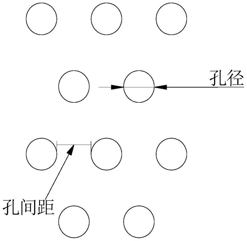
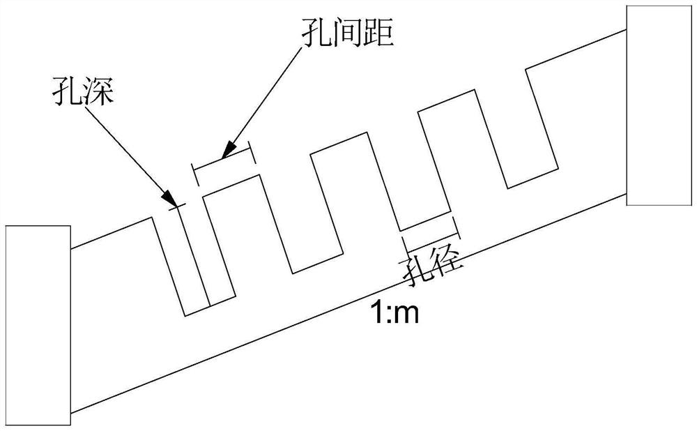
[0003] At present, there are many studies on cast-in-place greening concrete, such as CN106759389A discloses a construction method of cast-in-place greening concrete, which is beneficial to plant growth by opening vegetation holes on the surface, but it does not have different slopes and soil types in the slope environment. , pouring thickness and surface hole parameters (ie hole depth, hole diameter, hole spacing) design research, only proposed a surface hole technology, did not specify the parameters of specific applicable scenarios

Method used


Image

  • Cast-in-place greening concrete construction method for inland waterway
  • Cast-in-place greening concrete construction method for inland waterway

Examples


Embodiment 1

[0033] A cast-in-place greening concrete construction method for inland waterways, such as figure 1 , figure 2 shown, including the following steps:

[0034] 1) Make a cube mold with a length, width and height of 1m × 1m × 0.3m to simulate the slope, which can be supported by brackets and adjusted to different slopes. The soil quality of the simulated slope is clay, and the slope is 1:1.5. Lay 15cm thick clay in the mold, level and compact it with a compactor, and brush oil on the inner surface of the mold;

[0035] 2) Weigh the following components and masses and prepare them in order: 600 parts of aggregate, 120 parts of P.O 42.5 cement, 60 parts of water and 4 parts of special admixtures, the special admixtures are provided by Shanghai Jiuding Green Concrete Co., Ltd. Cast-in-place greening concrete with a thickness of 11cm is poured in the slope mold;

[0036] 3) Within 30 minutes after the completion of the pouring, use the drilling machine to open surface holes with ...


PUM

PropertyMeasurementUnit
Particle sizeaaaaaaaaaa
Lengthaaaaaaaaaa
Thicknessaaaaaaaaaa

Abstract

The invention discloses a cast-in-place greening concrete construction method for an inland waterway, which comprises the following steps of: 1) flattening and compacting a slope surface to be protected, and ensuring that the compaction degree is more than 90%; (2) aggregate, cement, water and a special additive are put into a stirring machine in sequence on site to be mixed to prepare greening concrete, the greening concrete is evenly poured on the slope surface according to the specified thickness, and surface holes are formed through a hole forming machine; (3) after maintenance is conducted for 5-7 days, planting soil and a water-retaining agent are scattered in surface holes and the slope surface; 4, grass seed sowing or turf laying is conducted on the part above the normal water level of the side slope, according to different gradients, slope lengths and soil types, the appropriate laying thickness and surface hole parameters of the cast-in-place greening concrete are provided, cost reduction and labor saving are facilitated, filtering and erosion of side slope soil can be reduced, water and soil flowing water can be reduced, and damage such as side slope landslide can be prevented.

Description

technical field [0001] The invention relates to the technical field of greening concrete slope protection, in particular to a cast-in-place greening concrete slope protection for inland waterways. Background technique [0002] The traditional slope protection forms of inland waterways mainly include rubble rubble, cast-in-place concrete, interlocking bricks, ecological cages, etc. The existing slope protection methods have poor structural stability and low ecological landscape benefits, and have a great impact on the slope soil and surrounding environment. , is not conducive to ecological sustainable development. In addition, due to wave erosion and water infiltration, the commonly used prefabricated component slope protection is prone to collapse, piping and other damages, increasing maintenance costs. In addition, the measures of laying textile materials such as geotextiles on the slope to maintain soil and water have many durability problems, the service life is short, a...

Claims


Application Information

Patent Timeline
IPC IPC(8): E02B3/12E02D15/00A01G20/00A01G22/00
CPCE02B3/12E02D15/00A01G20/00A01G22/00Y02A10/11
Inventor 李波张彤鑫康爱红宋关春林之涵寇长江吴正光
Owner YANGZHOU UNIV
Why Eureka
Try Eureka