Magnetized water structure and magnetized water production equipment with same

A technology of magnetized water and magnetic blocks, which is applied in the fields of magnetic field/electric field water/sewage treatment, etc., can solve the problems of loss of water flow rate, inability to quickly adjust magnetized water and non-magnetized water, and inability to produce magnetized water with magnetization intensity, and achieves a high level of improvement. The degree of intelligence and the effect of overcoming the loss of water flow velocity

Pending Publication Date: 2022-07-05
BENGBU SAIYA MACHINERY +1
View PDF8 Cites 0 Cited by
  • Summary
  • Abstract
  • Description
  • Claims
  • Application Information

AI Technical Summary

Problems solved by technology

[0003] However, the above-mentioned magnetizer still has relatively obvious defects in the use process: 1. The prior art and the above-mentioned magnetizer usually adopt the method of reducing the distance between the different-level magnets to increase the magnetic flux density while reducing the water flow rate. Furthermore, magnetized water with higher magnetization strength can be produced. However, in the prior art, the magnetization device that directly clamps and installs magnetization components on the pipeline without changing the shape of the pipeline is usually unable to produce due to the high magnetic flux density required for magnetized water. Therefore, the setting of the magnetization components of the two produces a certain contradiction, that is, the flow velocity of the pipeline after the magnetization components are installed is inversely proportional to the magnetization intensity, and in the actual use of magnetized water, usually only Regularly and quantitatively input a certain volume of magnetized water into the pipeline to meet the needs of industrial pipelines or agricultural irrigation and breeding, but the pipeline using the above-mentioned magnetizer greatly loses the water flow rate, and cannot quickly adjust magnetized water and non-magnetized water; 2. When the existing technology and the magnetization components of the above-mentioned devices are installed inside the pipeline network, the water flowing through the magnetization components will be completely magnetized. For the water bodies that only need partial magnetization or regular magnetization, the above-mentioned devices cannot be adjusted, and The timed shutdown of magnetized water cannot be realized, and the function is relatively simple

Method used


Image

  • Magnetized water structure and magnetized water production equipment with same
  • Magnetized water structure and magnetized water production equipment with same
  • Magnetized water structure and magnetized water production equipment with same

Examples


Embodiment 1

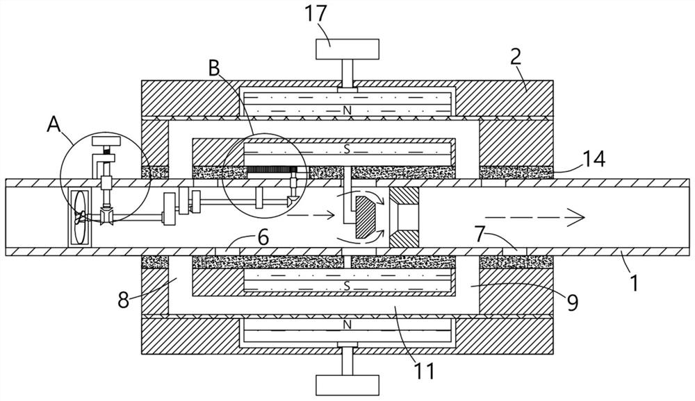
[0034] A magnetized water structure, comprising a confluence pipe 1, a magnetized water slide sleeve 2 is slidably sleeved on the outside of the confluence pipe 1, a sliding groove 3 is formed in the middle of the confluence pipe 1, and the magnetized water slide sleeve 2 is fixedly installed in the middle. The sliding groove 3 extends to the sealing block 4 inside the collecting pipe 1, and the sealing block 4 cooperates with the rubber ring 5 arranged inside the collecting pipe 1. The upper and lower sides of the collecting pipe 1 are also provided with magnetized water inlet holes 6 that penetrate inside and outside. The magnetized water outlet hole 7, the magnetized water inlet hole 6 and the magnetized water outlet hole 7 are respectively located on both sides of the rubber ring 5, and the magnetized water inlet hole 6 and the magnetized water outlet hole 7 are respectively opened with the upper and lower sides of the magnetized water sliding sleeve 2. The water inlet 8 an...

Embodiment 2

[0038] In this embodiment, a rubber sealing ring 14 is provided inside the magnetized water sliding sleeve 2 and the collecting pipe 1 on one side, and the magnetized water inlet hole 6 , the magnetized water outlet hole 7 and the The sliding groove 3 is blocked to prevent the water body from flowing out through the aforementioned channel.

Embodiment 3

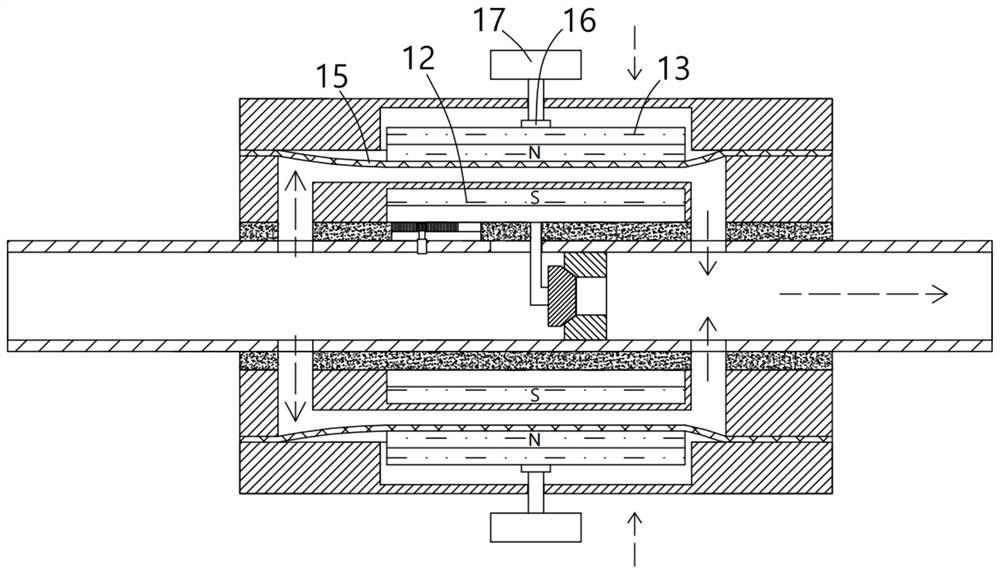
[0040] In this embodiment, the upper and lower movable magnetic blocks 13 are connected with flexible PVC spacers 15 on one side close to the fixed magnetic block 12 . The movement of the magnetic block 13 drives the flexible PVC partition layer 15 to expand and contract, and the flexible PVC partition layer 15 blocks the outflow of water.


PUM


Abstract

The invention provides a magnetized water structure and magnetized water production equipment with the same, the magnetized water structure comprises a collecting pipe, the collecting pipe is slidably sleeved with a magnetized water sliding sleeve, the middle part of the collecting pipe is provided with an internally and externally through sliding groove, and the middle part of the magnetized water sliding sleeve is fixedly provided with a sealing plug which penetrates through the sliding groove and extends into the collecting pipe; the magnetized water inlet hole and the magnetized water outlet hole are in sliding fit with a water inlet channel and a water outlet channel which are formed in the upper side and the lower side of the magnetized water sliding sleeve respectively, the magnetized water sliding sleeve is arranged outside the collecting pipe in a sliding and sleeving mode, the flowing path of a water body is adjusted through sliding of the magnetized water sliding sleeve, and then adjustment is conducted between magnetized water and non-magnetized water; the problem of water flow velocity loss caused by a fixed installation mode in the prior art is solved, a timing stop mechanism is arranged in a targeted mode, a path of water entering a magnetization channel is automatically cut off after a certain volume of magnetized water automatically flows through the interior of the collecting pipe, and the intelligent degree of the device is improved.

Description

technical field [0001] The invention relates to the technical field of magnetized water equipment, in particular to a magnetized water structure and a magnetized water production equipment having the structure. Background technique [0002] A magnetizer with the publication number "CN207845236U" in the prior art includes: a casing, a water passage horizontally passing through the inner cavity of the casing, a first magnetic block group and a second magnetic block group fixed on both sides of the water passage , and the shielding plate and the magnetic conducting plate arranged between the two magnet block groups and the inner wall of the casing, the number of magnet blocks in the two magnet block groups is the same, and the opposite poles are arranged oppositely, and the magnetic field of the adjacent magnet blocks in any magnet block group The directions are arranged in opposite directions. The water passage is a square flat tube with a square cross section. The end face of...

Claims


Application Information

Patent Timeline
Patent Type & Authority Applications(China)
IPC IPC(8): C02F1/48
CPCC02F1/48C02F2201/48
Inventor 王姚崔海伦武杰刘勇
Owner BENGBU SAIYA MACHINERY
Why Eureka
Try Eureka