Auxiliary equipment for building structure assembly

A technology for auxiliary equipment and building structures, applied in auxiliary welding equipment, welding/cutting auxiliary equipment, welding equipment, etc., can solve problems such as unfavorable steel bar fixing, waste of welding powder, and large manpower input, so as to save manual operation and improve The effect of work efficiency

Active Publication Date: 2022-07-05
ZHENGZHOU UNIV MULTI-FUNTIONAL DESIGN & RES ACAD CO LTD
View PDF6 Cites 0 Cited by
  • Summary
  • Abstract
  • Description
  • Claims
  • Application Information

AI Technical Summary

Problems solved by technology

[0003] The entire steel bar welding process requires a lot of manpower. The steel bar is first fixed with a clamp, and the clamp is removed from the steel bar later. It is necessary to repeatedly adjust the clamp by hand, which is time-consuming and laborious. It is not conducive to quickly fixing the steel bar with the clamp, and it is also difficult It is beneficial to quickly disassemble the fixture from the steel bar, and when disassembling the welding cylinder in the later stage, the traditional method is to dismantle it manually, and the excess welding flux will be spilled on the ground during disassembly, which not only wastes the flux, but also affects the work. The environment is clean and tidy

Method used


Image

  • Auxiliary equipment for building structure assembly
  • Auxiliary equipment for building structure assembly
  • Auxiliary equipment for building structure assembly

Examples


Embodiment Construction

[0035] The technical solutions in the embodiments of the present invention will be clearly and completely described below with reference to the embodiments of the present invention. Obviously, the described embodiments are only a part of the embodiments of the present invention, rather than all the embodiments. Based on the embodiments of the present invention, all other embodiments obtained by those of ordinary skill in the art without creative efforts shall fall within the protection scope of the present invention.

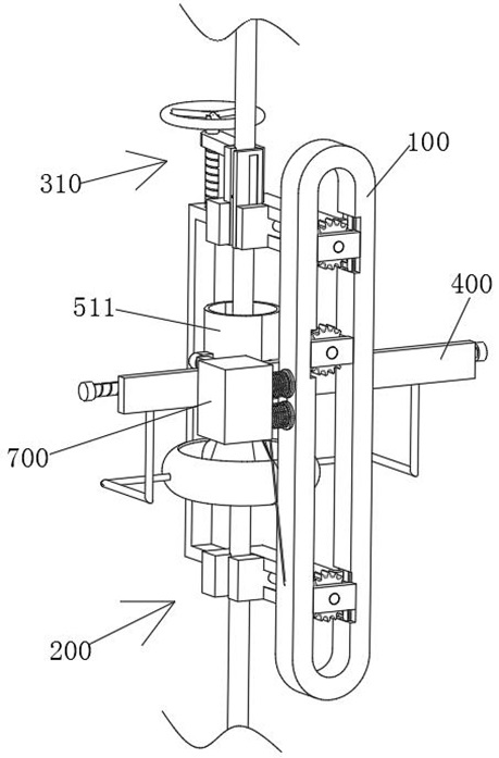
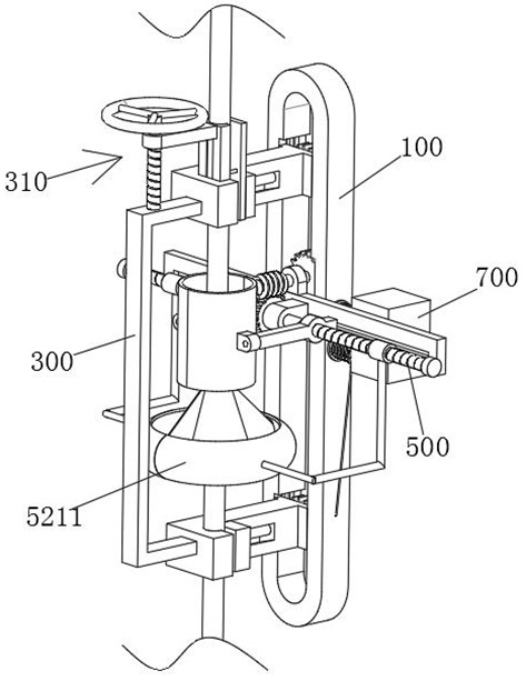
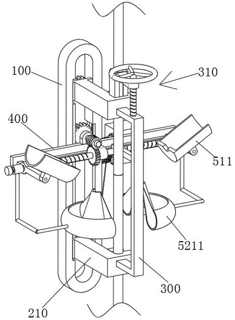
[0036] see Figure 1-13 As shown, an auxiliary device for building structure assembly includes a straight groove-shaped support frame 100, the top and bottom of the straight groove-shaped support frame 100 are provided with clamps 200, and two L-shaped splints 210 are fixed between two L-shaped splints 210. In the handle 300 , a guide plate 400 is fixed on one side of the straight groove-shaped support frame 100 , a bidirectional lead screw 500 is rotatably conn...


PUM


Abstract

The invention relates to the technical field of building construction, in particular to auxiliary equipment for building structure splicing, which comprises a straight-groove-shaped support frame, clamps are arranged at the top and the bottom of the straight-groove-shaped support frame, a [-shaped handle is fixed between two L-shaped clamping plates, a guide plate is fixed on one side of the straight-groove-shaped support frame, and the guide plate is fixed on the other side of the straight-groove-shaped support frame. The outer side of the guide plate is rotationally connected with a bidirectional lead screw, the top of the guide plate is rotationally connected with a transmission shaft used for driving the bidirectional lead screw to rotate, and the two ends of the middle of the bidirectional lead screw are connected with connecting rods in a screwed mode, and the connecting rods are in sliding connection with the guide plate. According to the device, the two connecting rods drive the welding barrel plates to move close to each other, the welding barrel composed of the two welding barrel plates is automatically connected to the butt joint position of the two steel bars in a sleeving mode, mechanical automation is achieved between clamping and fixing of the two steel bars and arrangement of the welding barrel, manual operation is omitted, and the working efficiency of fixing the steel bars and arranging the welding barrel can be improved.

Description

technical field [0001] The invention relates to the technical field of building construction, in particular to an auxiliary device used for building structure assembly. Background technique [0002] In architectural design and construction, the designer, according to the construction task, makes a comprehensive assumption in advance about the problems that exist or may need to be solved in the construction process, formulates methods and plans to solve these problems, and responds to the problems that need to be solved. The use of building construction aids to assist building construction. During the construction process, the steel bars will be lengthened according to the needs of the operation. The common method of lengthening the steel bars is to use electroslag pressure welding to lengthen the steel bars. The two steel bars are vertically butted and fixed, and then the welding barrel is sleeved at the butt position of the two steel bars, and the welding flux is placed in ...

Claims


Application Information

Patent Timeline
Patent Type & Authority Applications(China)
IPC IPC(8): B23K37/04B23K37/00B23K25/00B21F15/08
CPCB23K37/0435B23K37/00B23K25/00B21F15/08Y02E10/50
Inventor 梁献忠赵强王莉
Owner ZHENGZHOU UNIV MULTI-FUNTIONAL DESIGN & RES ACAD CO LTD
Why Eureka
Try Eureka