
Isolating switch

A technology of isolating switch and unit box, which is applied to circuit breaker contacts, protection switch operation/release mechanism, circuit breaker components, etc. and product cost, to achieve the effect of increasing the scope of applicable scenarios, improving reliability and safety, and reducing volume

Pending Publication Date: 2022-07-01
SHANGHAI LIANGXIN ELECTRICAL
View PDF0 Cites 0 Cited by
  • Summary
  • Abstract
  • Description
  • Claims
  • Application Information

AI Technical Summary

Problems solved by technology

[0004] The purpose of the present invention is to solve the problem that the contact modules of the existing rotary isolating switch are arranged in the vertical direction and cannot realize the tripping function or the tripping function needs to be realized by additional accessories, which increases the volume and product cost of the whole switch, and reduces To solve the defect of disconnector reliability, provide a disconnector, arrange the operating mechanism and contact system of the rotary switch in a horizontal direction, increase the applicable scene range of the rotary disconnector, and directly arrange the tripping functional parts inside the rotary disconnector , which not only reduces the size of the switch product, reduces the product cost, but also improves the reliability and safety of the isolating switch

Method used


Image

  • Isolating switch
  • Isolating switch
  • Isolating switch

Examples


Embodiment

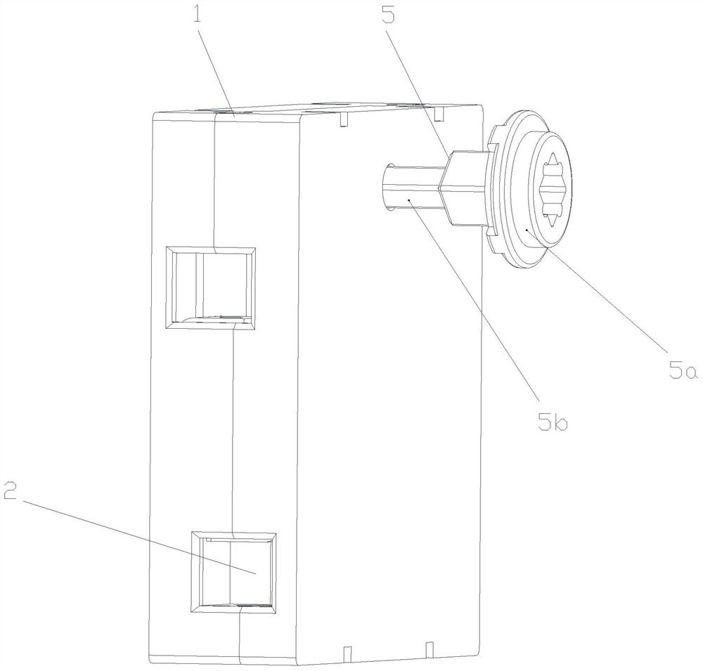
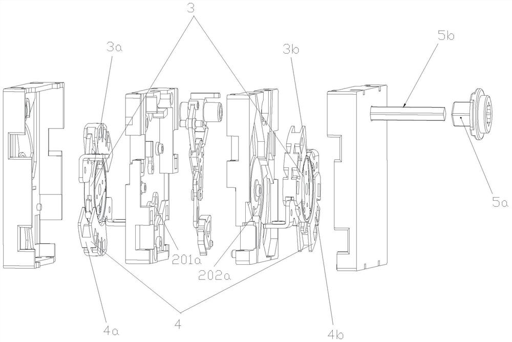
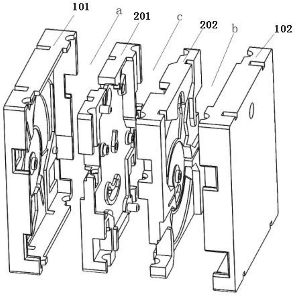
[0075] as attached figure 1 , as shown in 2, 3 and 4, an isolating switch, which includes a housing 1 and a unit box 2, the unit box 2 is installed in the inner cavity of the housing 1, the outer wall of the unit box 2 and all the The inner wall of the corresponding side of the casing 1 forms a cavity a, the outer wall of the other side of the unit box 2 and the inner wall of the corresponding other side of the casing 1 form a cavity 2 b, and the unit box 2 is provided with a cavity 3. c, the cavity 1 a and the cavity 2 b are located on both sides of the cavity 3 c, the operating mechanism is installed in the cavity 3 c, and the contact system 3 and the arc extinguishing chamber 4 are installed in the cavity In the first a and the second cavity b, the handle assembly 5 includes a handle 5a and a handle link 5b, and the handle link 5b is fixedly connected to the handle shaft 8 through the through holes on the housing 1 and the unit box 2 . as attached Figure 18 As shown, th...


PUM


Abstract

A disconnecting switch is characterized in that the disconnecting switch comprises a shell and a unit box, the unit box is arranged in an inner cavity of the shell, the outer wall of one side of the unit box and the inner wall of the corresponding side of the shell form a first cavity, the outer wall of the other side of the unit box and the inner wall of the corresponding side of the shell form a second cavity, a third cavity is arranged in the unit box, and the second cavity is communicated with the third cavity. The first cavity and the second cavity are located on the two sides of the third cavity, the operating mechanism is installed in the third cavity, and the contact system and the arc extinguish chamber are installed in the first cavity and the second cavity. The operating mechanism and the contact system of the rotary switch are arranged in the horizontal direction, the applicable scene range of the rotary disconnecting switch is increased, the tripping function component is directly arranged in the rotary disconnecting switch, the size of a switch product is reduced, the product cost is reduced, and meanwhile the use reliability and safety of the disconnecting switch are improved.

Description

technical field [0001] The invention belongs to the technical field of switches, and specifically relates to an isolation switch. Background technique [0002] The word switch is interpreted as on and off. It refers to an element that can open a circuit, interrupt current, or cause it to flow to other circuits. The most common switches are human-operated electromechanical devices that have one or more contacts. The "closed" of the contact means that the contact is conducting, allowing current to flow; the "open" of the switch means that the contact is not conducting to form an open circuit, which does not allow current to flow. The development history of the switch has evolved from the original knife switch that requires manual operation to the current intelligent switch used in various large-scale electrical control equipment. Isolation switch is a low-voltage electrical device commonly used in circuits, which can change its on / off state by front operation or side operat...

Claims


Application Information

Patent Timeline
Patent Type & Authority Applications(China)
IPC IPC(8): H01H71/10H01H73/04H01H73/18H01H71/12
CPCH01H71/10H01H73/04H01H73/18H01H71/128
Inventor 彭琼向洪岗
Owner SHANGHAI LIANGXIN ELECTRICAL
Learn More