Clean energy hydrogen and ammonia production system
A technology for clean energy and hydrogen production system, applied in the field of clean energy hydrogen production and ammonia production system, can solve the problems of carbon dioxide emission and non-renewable resource consumption, and achieve the effect of solving carbon emission, realizing long-distance efficient transportation and reducing consumption
- Summary
- Abstract
- Description
- Claims
- Application Information
AI Technical Summary
Problems solved by technology
Method used
Image

Examples
Embodiment 1
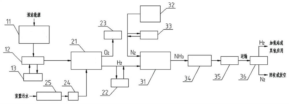
[0027] A clean energy electrolysis hydrogen production and ammonia production system includes a power supply system, a water electrolysis hydrogen production system and a synthetic ammonia system. The power supply system includes a clean energy generator and a peak regulation control system; the water electrolysis hydrogen production system includes a water electrolysis device and a water supply system; the synthetic ammonia system includes a synthetic ammonia device, an air separation device and an ammonia storage system.
[0028] like figure 1As shown, the power generation output end of the clean energy generator 11 is connected to the power input end of the water electrolysis device 21 , and the clean energy generator 11 is controlled by the peak regulation control system 12 . When the clean energy is sufficient, the electricity obtained by the clean energy generator 11 is preferentially used by the water supply and electrolysis device 21. When there is surplus electricity,...
Embodiment 2
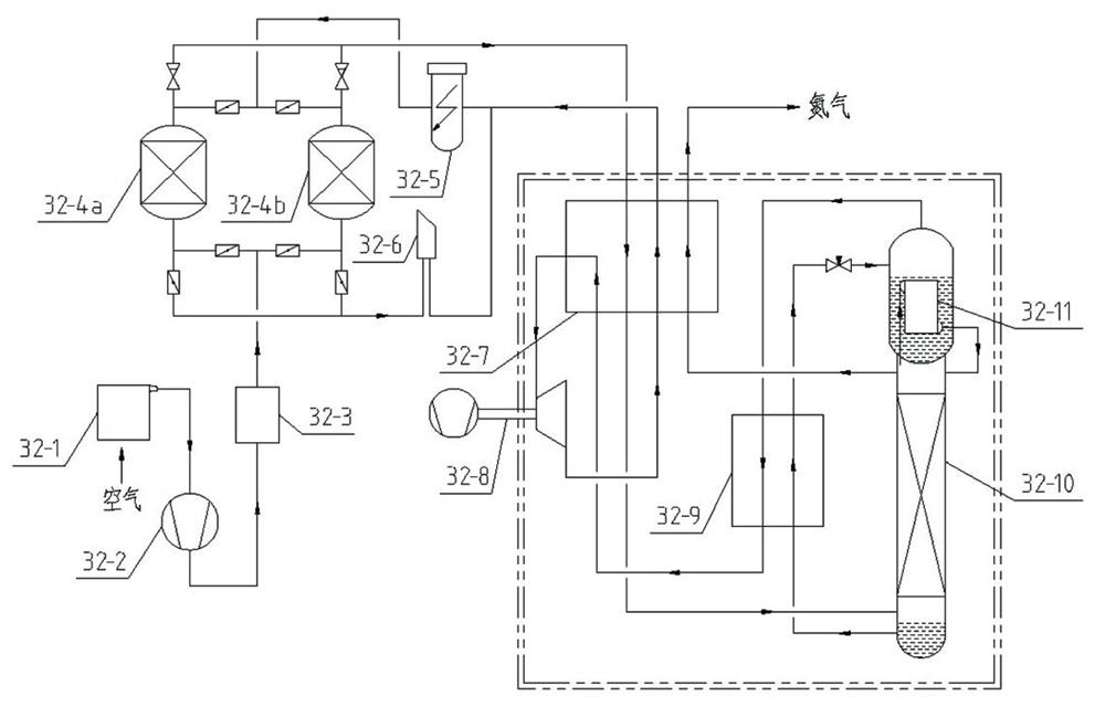
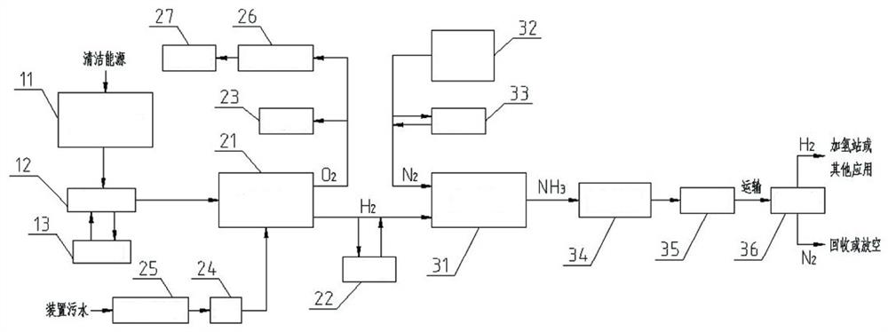
[0033] like image 3 As shown, on the basis of Embodiment 1, the oxygen outlet of the water electrolysis device is connected to the liquid oxygen storage tank 27 through the oxygen liquefaction device 26, and the oxygen produced by the water electrolysis device 21 is liquefied and stored in the liquid oxygen storage tank in the form of liquid oxygen. In tank 27, liquid oxygen can be sold as a by-product.
Embodiment 3
[0035] like Figure 4 As shown, on the basis of embodiment two, the ammonia gas outlet of the synthetic ammonia device 31 is also connected with the ammonia gas storage tank 38, and the ammonia gas storage tank 38 outlet is connected with the chemical plant that takes ammonia as a raw material, and provides raw material ammonia for chemical production, such as Production of chemical products such as urea and nitric acid, or filling and selling. Part of the ammonia gas is liquefied by the ammonia liquefaction device 34 and then transported to other chemical plants, and after re-vaporization, provides raw material ammonia for chemical production.
[0036] To sum up, the present invention realizes the zero-carbon emission production of hydrogen through clean energy power generation and water electrolysis technology, and at the same time couples with the synthetic ammonia technology to transfer the dangerous hydrogen, which is difficult to store and transport, into ammonia, in the...
PUM
 Abstract
Description
Claims
Application Information
 - R&D
- Intellectual Property
- Life Sciences
- Materials
- Tech Scout
- Unparalleled Data Quality
- Higher Quality Content
- 60% Fewer Hallucinations
Browse by: Latest US Patents, China's latest patents, Technical Efficacy Thesaurus, Application Domain, Technology Topic, Popular Technical Reports.
© 2025 PatSnap. All rights reserved.Legal|Privacy policy|Modern Slavery Act Transparency Statement|Sitemap|About US| Contact US: help@patsnap.com