Boundary stiffness simulation system in full-dynamic vertical fin buffeting test for airplane strength test
An aircraft strength and stiffness simulation technology, which is applied in the direction of aircraft component testing, mechanical component testing, machine/structural component testing, etc., can solve problems such as inconsistency, inconsistency of main modal frequencies, and failure to consider boundary dynamic stiffness, etc., to improve The effect of overall reliability and simple structure
- Summary
- Abstract
- Description
- Claims
- Application Information
AI Technical Summary
Problems solved by technology
Method used
Image
Examples
Embodiment 1
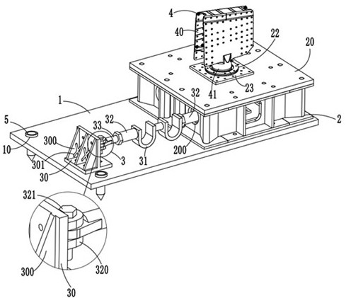
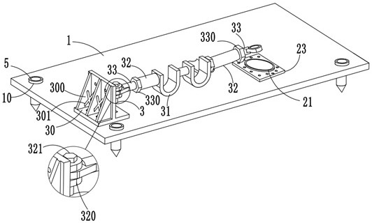
[0035] like figure 1 , 2 As shown, the boundary stiffness simulation system in the full-motion vertical tail buffeting test of the aircraft strength test includes a mounting base plate 1 connected to the ground through anchor bolts, and a mounting base plate 1 which is installed on the mounting base plate 1 and used to simulate the bending boundary motion of the full-motion vertical tail. Boundary dynamic stiffness simulation component 2 for stiffness, rotational dynamic stiffness simulation component 3 located on the mounting base plate 1 and used to simulate the rotational dynamic stiffness of the full-moving vertical tail, boundary dynamic stiffness simulation component 2 and rotational dynamic stiffness simulation component 3 and the vertical dynamic stiffness of the aircraft. tail 4 connection;
[0036] Three reinforcing plates 300 are arranged between the connection base 30 and the installation bottom plate 1, and two reinforcing beams 301 are arranged crosswise between...
Embodiment 2
[0044] This embodiment differs from Embodiment 1 in that:
[0045] The sections of the elastic adjustment section 310 and the thickness increasing plate 313 are annular, and the thickness increasing plate 313 is clamped to the inner wall of the elastic adjustment section 310 .
Embodiment 3
[0047] This embodiment differs from Embodiment 2 in that:
[0048] like figure 1 , 6 As shown, the mounting base 1 is provided with four mounting ports 10, and each mounting port 10 is provided with a fastening connection device 5, and the fastening connection device 5 includes a snap-on connection in the mounting port 10 and a conical head 500 at the bottom. The T-type fastening main body 50, the fastening installation cavity 51 provided in the T-type fastening main body 50, the four radially distributed in the circumferential direction of the T-type fastening main body 50 and the first socket 520 is provided through the side wall. The tightening rod 52 and the moving adjusting rod 53 are arranged in the tightening installation cavity 51 and have a tip 530 at the bottom. The outer wall of the T-shaped tightening body 50 is provided with a one-to-one correspondence with the tightening rod 52 and with the tightening installation cavity. The sliding port 501 penetrates through...
PUM
 Abstract
Description
Claims
Application Information
 - R&D Engineer
- R&D Manager
- IP Professional
- Industry Leading Data Capabilities
- Powerful AI technology
- Patent DNA Extraction
Browse by: Latest US Patents, China's latest patents, Technical Efficacy Thesaurus, Application Domain, Technology Topic, Popular Technical Reports.
© 2024 PatSnap. All rights reserved.Legal|Privacy policy|Modern Slavery Act Transparency Statement|Sitemap|About US| Contact US: help@patsnap.com


