Gap drainage blade type diffuser for centrifugal pump

A diffuser and vane type technology is applied in the field of slit drainage vane diffusers for centrifugal pumps, and can solve the problems of reducing the flow stability of the diffuser, weakening the pressure recovery of the diffuser, affecting the safety and efficiency of operation, etc. Achieve the effect of improving the circumferential unevenness of the flow field, reducing the risk of stalling, and being easy to process and implement.

Pending Publication Date: 2022-06-28
SHANDONG JIANZHU UNIV
View PDF4 Cites 0 Cited by
  • Summary
  • Abstract
  • Description
  • Claims
  • Application Information

AI Technical Summary

Problems solved by technology

Existing vane diffusers usually only have a number of fixed seamless guide vanes. When the operation deviates from the optimal operating point, there is an attack angle at the leading edge of the guide vanes, and a vortex induced by flow separation appears inside the diffuser, seriously The rotation stall in the diffuser will increase the flow loss, reduce the flow stability in the diffuser, generate vibration and noise of different frequencies, and weaken the pressure recovery of the diffuser and the reduction of the radial force of the impeller. ability
Secondly, even under the optimal working condition, if the installation angle of the diffuser is unreasonable, under the influence of the timing effect, the flow channel of the diffuser at the tongue of the volute is likely to generate clogging vortices, resulting in distortion of the flow field and affecting the operation. safety and efficiency
Therefore, there are still some deficiencies in the design of the existing guide vane, which is difficult to meet the production requirements, and it is necessary to further explore its structure

Method used


Image

  • Gap drainage blade type diffuser for centrifugal pump
  • Gap drainage blade type diffuser for centrifugal pump
  • Gap drainage blade type diffuser for centrifugal pump

Examples


Embodiment 1

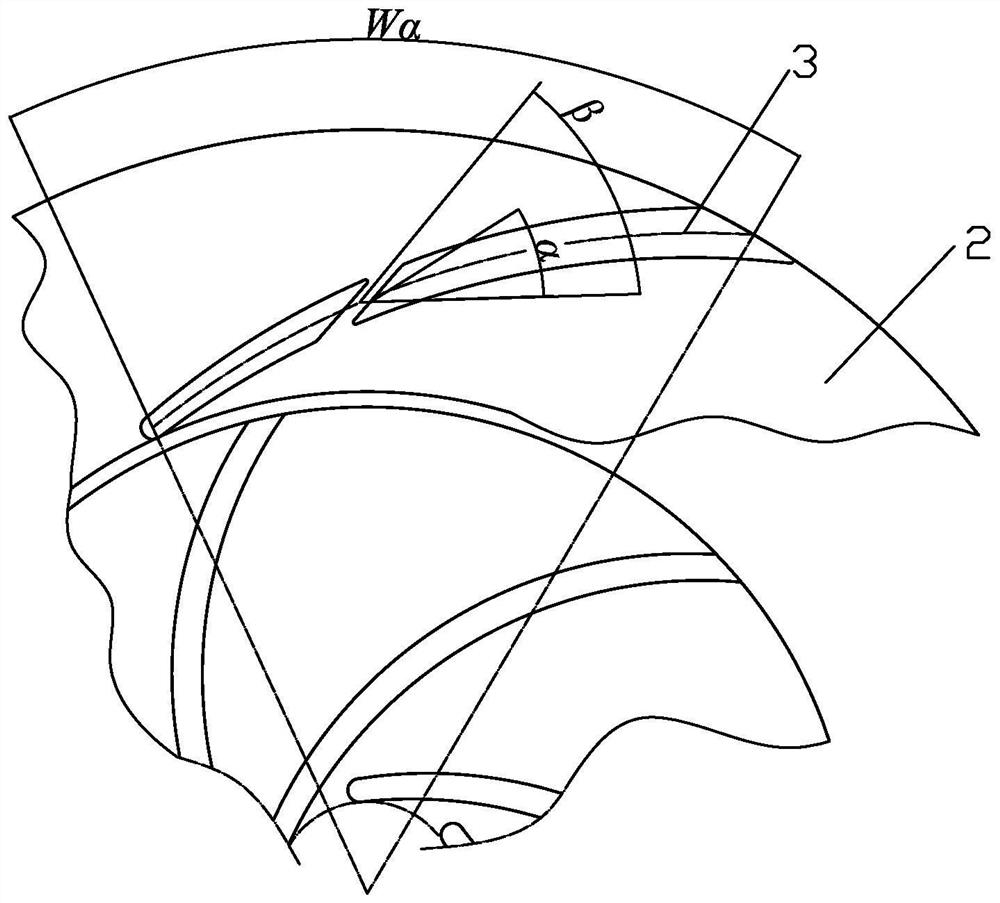
[0033] The blade wrap angle Wa=58°, the length of the bone line l=66mm, the length of the slit from the inlet edge bone line l1=30mm, the blade placement angle α=12.7° based on the bone line at the slit, the inclination angle of the slit β=50.3°, Slot width b2=2.4mm, blade width b1=2.6mm at the slit,

[0034] According to the formula lc=l1 / l of the relative position of the gap, lc=30 / l=0.455,

[0035] According to the calculation formula bc=b2 / b1 of the relative width of the gap, it can be calculated that bc=2.4 / 2.6=0.923,

[0036] According to the calculation formula θ=(β+α) / α of the relative inclination coefficient of the slot, θ=(50.3°+12.7°) / 12.7°=4.96° can be obtained.

Embodiment 2

[0038] The blade wrap angle Wa=55°, the length of the bone line l=76.6mm, the length l1=29.5mm between the slit and the bone line of the inlet side, the blade placement angle at the slit is based on the bone line α=22°, the inclination angle of the slit β=48 °, the slit width b2=3mm, the blade width b1=4.5mm at the slit;

[0039] According to the calculation formula lc=l1 / l of the relative position of the gap, it can be obtained that lc=0.385,

[0040] According to the calculation formula bc=b2 / b1 of the relative width of the gap, it can be obtained that bc=0.667,

[0041] According to the calculation formula θ=(β+α) / α of the relative inclination coefficient of the gap, it can be obtained that θ=3.182,

Embodiment 3

[0043] The blade wrap angle Wa=66°, the length of the bone line l=180mm, the length of the slit from the inlet edge bone line l1=111.6mm, the blade placement angle at the slit is based on the bone line α=12°, the inclination angle of the slit β=36° , the width of the slit is b2=4.5mm, and the width of the blade at the slit is b1=7.5mm;

[0044] According to the calculation formula lc=l1 / l of the relative position of the gap, it can be obtained that lc=0.62,

[0045] According to the calculation formula bc=b2 / b1 of the relative width of the gap, it can be obtained that bc=0.6,

[0046] According to the calculation formula θ=(β+α) / α of the relative inclination coefficient of the gap, it can be obtained that θ=4,

[0047] The following table is a comparison table of comprehensive indicators before and after improvement:

[0048] Performance parameters of centrifugal pumps using traditional guide vanes:

[0049]

[0050] Use the performance parameters of the centrifugal pump...


PUM


Abstract

The gap drainage blade type diffuser for the centrifugal pump structurally comprises a front cover plate and a rear cover plate which are oppositely arranged in parallel, and is characterized in that a plurality of guide blades are arranged between the front cover plate and the rear cover plate, the front cover plate, the rear cover plate and the guide blades form a plurality of flow channels, and the flow channels are communicated with the front cover plate and the rear cover plate. And the radial middle part of the guide vane is slotted. Flow channels on the two sides of the blade are communicated through guide blade slots, flow separation on the surface of the blade can be effectively controlled and improved through drainage of the inner slots, separation vortexes are eliminated, the stall risk is reduced, and diffusion stability is improved. Therefore, the internal flow field and the blade load are redistributed when the deflection working condition or the circumferential placement angle of the diffuser is inappropriate. The phenomenon that a flow field in the diffuser is uneven in the circumferential direction is effectively improved, the unsteady speed and pressure pulsation of the flow field of the diffuser are reduced, and radial alternating stress borne by an impeller is reduced. The overall stability is improved, and the service life is prolonged.

Description

technical field [0001] The invention relates to the technical field of hydraulic machinery, in particular to a slit drainage vane type diffuser for a centrifugal pump. Background technique [0002] As an important overcurrent component to reduce the radial alternating stress of the impeller and improve the safety and stability of the centrifugal pump, the vane diffuser is widely used in the pumping station system in the field of national economy. Due to the high-speed rotation of the centrifugal impeller, the mechanical energy of the rotating shaft is converted into the kinetic energy and pressure energy of the liquid under the action of centrifugal force. While regulating the fluid flow, the downstream diffuser further converts the kinetic energy of the fluid into pressure energy for pressure recovery, and at the same time reduces the dynamic and static interference between the volute tongue and the impeller, reduces the pressure pulsation in the flow field and acts on the ...

Claims


Application Information

Patent Timeline
Patent Type & Authority Applications(China)
IPC IPC(8): F04D29/44F04D29/66F04D29/68
CPCF04D29/448F04D29/669F04D29/688
Inventor 朱相源刘吉营张谦王玉博
Owner SHANDONG JIANZHU UNIV
Why Eureka
Try Eureka