High-pressure rapid long-stroke hydraulic machine
A long-stroke, hydraulic press technology, applied in the field of hydraulic presses, can solve problems such as limited impact force, slow elongation speed, difficult processing, etc., and achieve the effect of increasing stroke and speed
- Summary
- Abstract
- Description
- Claims
- Application Information
AI Technical Summary
Problems solved by technology
Method used
Image

Examples
Embodiment 1
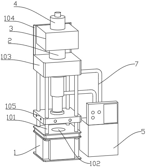
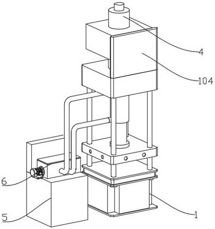
[0034] Please refer to Figures 1-3, a high-pressure fast long-stroke hydraulic press, including a base 1 and an oil pump 5, the top four corners of the base 1 are inserted with uprights 101, the top of the uprights 101 is provided with an upper beam 103, and the interior of the base 1 is provided with a top Out of the cylinder 102, the top rear end of the upper beam 103 is welded with a back plate 104, the front end of the back plate 104 is fixed with a pressurized chamber 3, and the bottom of the pressurized chamber 3 is connected with a multi-stage hydraulic cylinder 2, and the The bottom is connected with a movable beam 105, the movable beam 105 is passed through by the column 101, and the top of the pressurized bin 3 is connected with an air storage chamber 4;
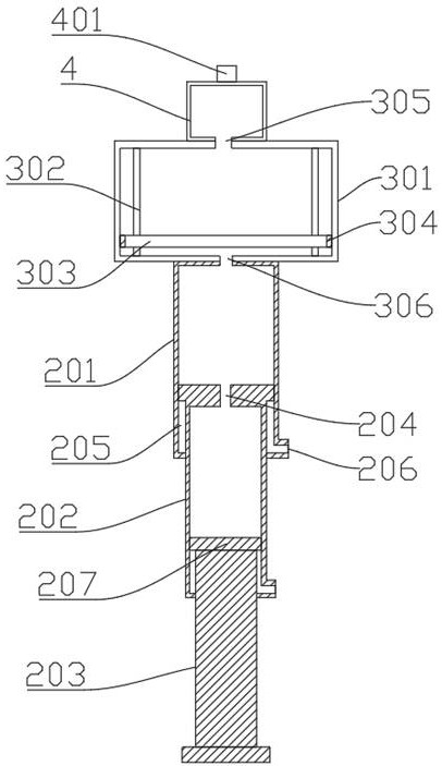
[0035] The multi-stage hydraulic cylinder 2 includes a master cylinder 201, a primary rod 202 is inserted at the bottom of the master cylinder 201, an oil hole 206 is provided on the outer sides of the bottom of the...
Embodiment 2
[0042] Please refer to Figures 3-4. The difference from Embodiment 1 is that a check valve 401 is threadedly connected to the top of the air storage chamber 4, and the top of the check valve 401 is connected to the air pumping device. The check valve 401 includes a valve body 402. The two ends of the valve body 402 are provided with threaded rings 404, the inside of the valve body 402 is provided with through holes 403, the bottom inner wall of the valve body 402 is welded with a transverse rod 405, and the top of the middle of the transverse rod 405 is welded with a longitudinal rod 406. The outer side of 406 is sleeved with a spring 407, the bottom of the spring 407 is connected to the top of the cross bar 405, the top of the spring 407 is provided with a movable plug 408, the movable plug 408 is in contact with the through hole 403 and the outer diameter of the movable plug 408 is larger than the through hole 403 the inner diameter.
[0043] When the internal air pressure o...
Embodiment 3
[0046] Referring to Figures 5-6, the difference from Embodiment 2 is that the flow direction controller 6 includes a casing 601, an outer end of one side of the casing 601 is connected with a motor 602, and an oil inlet pipe 605 is inserted into the front end of the casing 601. The oil inlet pipe 605 is connected to the oil pump 5 , two oil outlet pipes 7 are inserted at the rear end of the housing 601 , the output end of the motor 602 is fixedly connected with a screw rod 603 , and a moving block 604 is sleeved on the outer side of the screw rod 603 .
[0047] The moving block 604, one end of the oil inlet pipe 605 close to the moving block 604, and one end of the oil outlet pipe 7 close to the moving block 604 are at the same level. When the pipes are not aligned, the oil pipe will be blocked by the moving block 604. The through-pipe 606 and the two elbows 607 located at both ends of the tee-pipe 606 have three outlets, one of which is communicated with the oil inlet pipe 605...
PUM
 Abstract
Description
Claims
Application Information
 - R&D
- Intellectual Property
- Life Sciences
- Materials
- Tech Scout
- Unparalleled Data Quality
- Higher Quality Content
- 60% Fewer Hallucinations
Browse by: Latest US Patents, China's latest patents, Technical Efficacy Thesaurus, Application Domain, Technology Topic, Popular Technical Reports.
© 2025 PatSnap. All rights reserved.Legal|Privacy policy|Modern Slavery Act Transparency Statement|Sitemap|About US| Contact US: help@patsnap.com