Suspension type accelerator pedal sensor shaft mounting device and method
An accelerator pedal and sensor technology, which is applied in metal processing equipment, metal processing, manufacturing tools, etc., can solve the problems of broken sensor shaft, difficult assembly, and difficult operation, and achieves high installation accuracy, high press-fitting accuracy, and improved pressure The effect of fit
- Summary
- Abstract
- Description
- Claims
- Application Information
AI Technical Summary
Problems solved by technology
Method used
Image
Examples
Embodiment approach 1
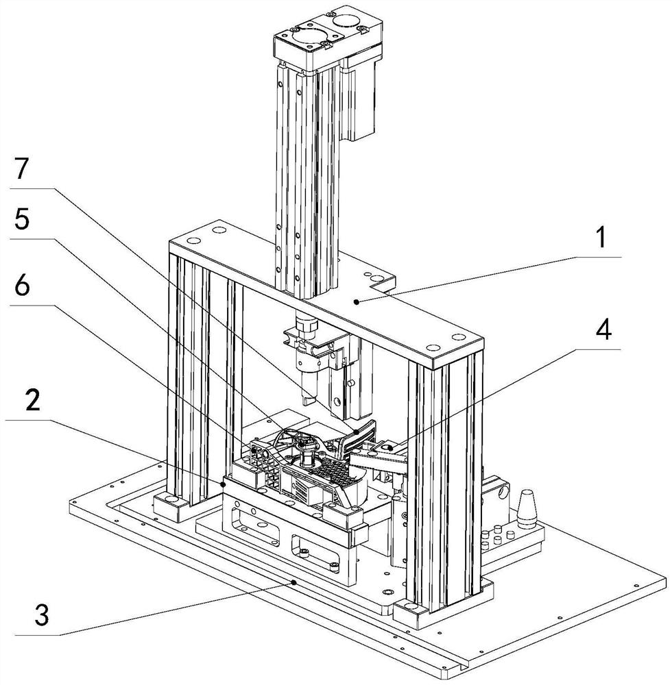
[0040] see figure 1 , this embodiment provides a suspension type accelerator pedal sensor shaft installation device for press-fitting the sensor shaft 5 into the accelerator pedal (the accelerator base 6 and the accelerator link 7), including a base plate 3, a pressing mechanism 1, a placement device Mechanism 2 and side push mechanism 4.
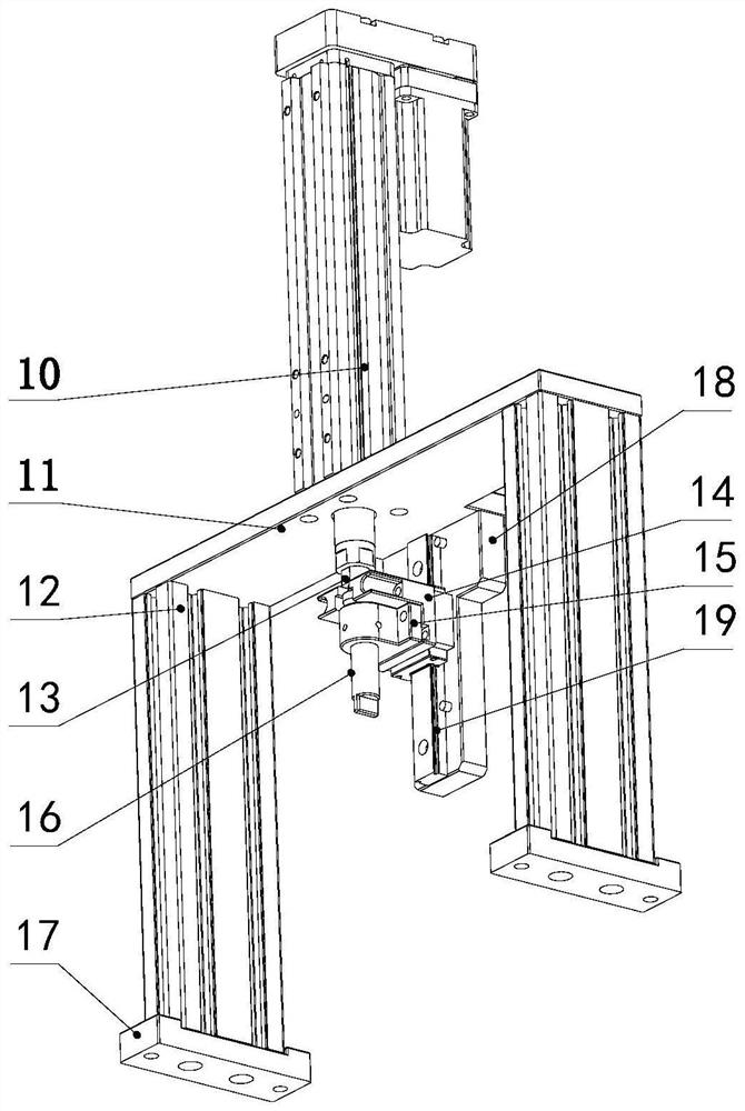
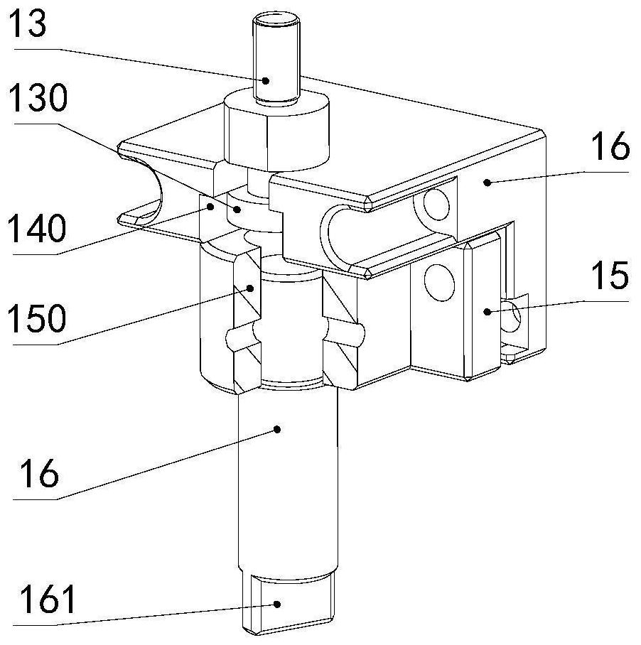
[0041] see Figure 2 to Figure 4 , the pressing mechanism 1 includes a servo electric cylinder 10 , a gantry, a floating head 13 , an L-shaped plate 14 , a pressing head seat 15 , a pressing head 16 , a linear guide 19 and a guide plate 18 .
[0042] The gantry frame is composed of a gantry board 11, a profile 12 and a profile seat 17. The two profiles 12 are arranged in parallel under the two sides of the gantry board 11, and the lower ends are respectively inserted into the slots of the profile seat 17; the servo electric cylinder 10 is installed vertically Just above the gantry plate 11 , the extension rod of the electric cylinder goes...
Embodiment approach 2
[0056] see figure 1 and Figure 12 , this embodiment provides a method for using the accelerator sensor shaft installation device as described in Embodiment 1, which is characterized in that it includes the following steps:
[0057] The first step is to place the loose electronic throttle assembly into the product positioning device 2, so that the lower side of the throttle base 6 fits the contoured surface 2130, the lower hole 64 of the throttle base 6, the sensor shaft hole of the throttle link 7, the throttle The upper hole 63 of the base 6 passes through the positioning post 210 in turn, and the technological hole 70 of the accelerator connecting rod 7 is inserted into the rotating pin 22; the compression cylinder 21 is activated, the cylinder piston rod retracts, and the pressure head 22 moves downward to contact the throttle base 6. On the upper side, press the throttle base 6 on the profiling surface 2130;
[0058] The second step is to start the dual-axis cylinder 46...
PUM
 Abstract
Description
Claims
Application Information
 - R&D
- Intellectual Property
- Life Sciences
- Materials
- Tech Scout
- Unparalleled Data Quality
- Higher Quality Content
- 60% Fewer Hallucinations
Browse by: Latest US Patents, China's latest patents, Technical Efficacy Thesaurus, Application Domain, Technology Topic, Popular Technical Reports.
© 2025 PatSnap. All rights reserved.Legal|Privacy policy|Modern Slavery Act Transparency Statement|Sitemap|About US| Contact US: help@patsnap.com


