
Interlayer light-emitting glass device and automobile skylight

A luminous glass and interlayer technology, applied in the field of lighting, can solve the problems of reducing durability, reducing glass permeability and durability, etc., and achieve the effects of high transparency, various quality improvements, and reduced loss

Pending Publication Date: 2022-06-24
浙江彩丞科技有限公司
View PDF14 Cites 0 Cited by
  • Summary
  • Abstract
  • Description
  • Claims
  • Application Information

AI Technical Summary

Problems solved by technology

[0009] In the existing technology, light is directly pasted on the glass surface through a light-transmitting film, and the microstructure directly contacts the outside world, which reduces the durability
And another existing technology directly processes the microstructure on the glass, which reduces the permeability and durability of the glass

Method used


Image

  • Interlayer light-emitting glass device and automobile skylight
  • Interlayer light-emitting glass device and automobile skylight
  • Interlayer light-emitting glass device and automobile skylight

Examples


Embodiment 1

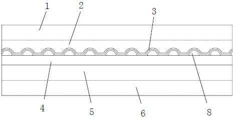
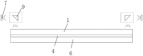
[0038] see Figures 1 to 4 The core of the present invention is to provide a laminated light-emitting glass device, including a light source component and a light-emitting glass component. The light source component is used to provide light and is arranged on the light-incident side of the light-emitting glass component. , to make it glow.

[0039] The light source assembly includes an LED lamp 7 and an introduction device. The LED lamp 7 provides light and is introduced into the light-emitting glass assembly through the introduction device. The introduction means may be one or more of gratings, prisms 9 and microstructures. And the light introduction method can be side incident light, forward incident light, or a combination of the two. The light source component can be arranged on the side or the front of the light-emitting glass component, that is to say, the light-incident side of the light-emitting glass component can be on the side of the light-emitting glass component....

Embodiment 2

[0054] Another core of the present invention is to provide an automobile sunroof, which adopts the laminated light-emitting glass device of Embodiment 1. The laminated light-emitting glass device is arranged in the hollow of the top of the automobile. Buckles, such as U-shaped buckles, are mounted directly on the side walls of the luminous glass assembly. The laminated light-emitting glass device can make the entire light-emitting glass component emit light uniformly when light is introduced, and the light-emitting glass component is transparent when no light is introduced, which can be used as ordinary glass and can also be used for lighting. Used as a car sunroof, it does not affect the sight of the sunroof when the light is off, and it is almost completely transparent. When the light is on, the entire sunroof is illuminated to achieve the effect of interior lighting.


PUM


Abstract

The invention discloses an interlayer light-emitting glass device which comprises a light source assembly and a light-emitting glass assembly, the light source assembly is used for providing light rays and is arranged on the light incident side of the light-emitting glass assembly, and the light rays are incident into the light-emitting glass assembly from the light incident side; the light-emitting glass assembly sequentially comprises a first glass layer, a first bonding layer, a protective layer, a microstructure layer, a second bonding layer and a second glass layer, a plurality of microstructures are arranged on one surface of the microstructure layer, and the protective layer is arranged on the surface, provided with the microstructures, of the microstructure layer. The first glass layer and the second glass layer are attached to the other surface of the protective layer and the other surface of the microstructure layer through the first bonding layer and the second bonding layer respectively. The light enters the luminescent glass assembly and is scattered by the microstructure when being conducted to the microstructure, and the scattered light is emitted from the first glass layer. The device is very durable and has good permeability under the condition that light is not guided in.

Description

technical field [0001] The invention belongs to the technical field of lighting, and in particular relates to a laminated light-emitting glass device and an automobile sunroof. Background technique [0002] Light-emitting glass is to process light guide points on the glass surface by etching, hot pressing or printing, and guide light into the glass through the LED light source. [0003] Fuyao Glass Industry Group Co., Ltd. disclosed a photoluminescent laminated glass in 201410208093.7, comprising a first glass substrate, a second glass substrate and an intermediate layer sandwiched between the first glass substrate and the second glass substrate, The intermediate layer has a first surface and a second surface facing opposite, and the intermediate layer is dispersed with inorganic compound phosphors from the first surface and / or the second surface to the interior of the intermediate layer, and the dispersion concentration is from The first surface or the second surface begin...

Claims


Application Information

Patent Timeline
IPC IPC(8): F21V21/00F21V7/00F21V33/00B32B3/28B32B17/10B32B33/00B32B27/36B32B27/30B32B7/12B32B1/00B60J7/00F21W107/10F21W106/00F21V8/00
CPCF21V21/00F21V7/00F21V33/00B32B1/00B32B3/28B32B17/10779B32B17/1055B32B17/10743B32B17/10752B32B33/00B32B7/12B32B27/36B32B27/365B32B27/302B32B27/308B32B27/304B60J7/00B32B2307/40B32B2307/304B32B2307/71F21V2200/00F21W2107/10F21W2106/00
Inventor 孙利强林友建谭之海彭书鑫
Owner 浙江彩丞科技有限公司
Learn More