
Siphon type purification and pollution discharge device for kitchen sink

A technology for kitchen sinks and sewage devices, applied in water supply devices, indoor sanitary plumbing devices, buildings, etc., can solve problems such as sewer pipe blockage, achieve full contact, and improve the effect of adsorption and decomposition

Active Publication Date: 2022-06-24
XIAMEN UNIV OF TECH
View PDF4 Cites 0 Cited by
  • Summary
  • Abstract
  • Description
  • Claims
  • Application Information

AI Technical Summary

Problems solved by technology

[0003] Aiming at the deficiencies of the prior art, the present invention provides a siphon purification and sewage device for kitchen sinks, which mainly solves the problem that the existing domestic sewage is directly discharged into the sewer pipe only through simple filtration, which is still easy to cause blockage of the sewer pipe technical problem

Method used


Image

  • Siphon type purification and pollution discharge device for kitchen sink
  • Siphon type purification and pollution discharge device for kitchen sink

Examples


Embodiment 1

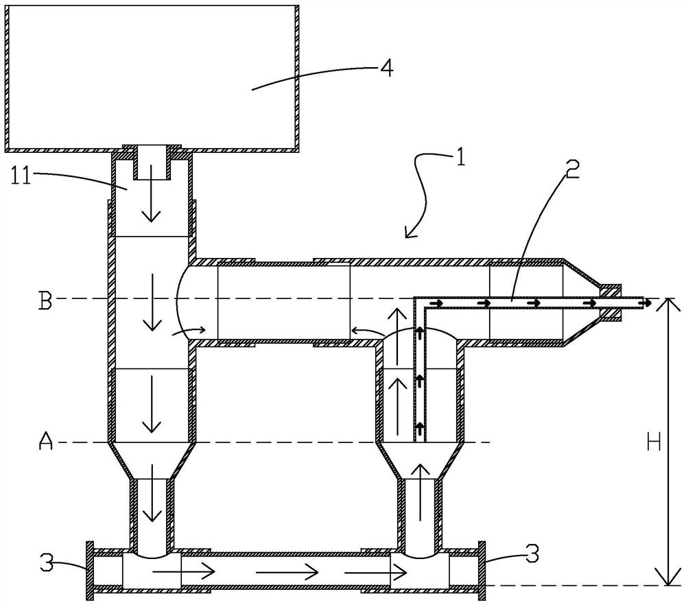
[0024] Please refer to the attached figure 1 One embodiment of the present invention provides a siphon-type sewage purification and sewage device for a kitchen sink, comprising a water storage pipe main body 1 connected by a plurality of pipes to form a substantially back-shaped structure, and a top of one side of the water storage pipe main body 1 is formed with a The water inlet 11 connected to the water tank 4 has a siphon drain pipe 2 on the other side of the water storage pipe body 1 away from the water inlet 11, and the outlet end of the siphon drain pipe 2 penetrates the water storage pipe main body 1 in a sealed manner toward the side. And the installation height of the outlet end of the siphon sewage pipe 2 is configured to be slightly lower than the water inlet 11 on the main body 1 of the water storage pipe, and the inlet end of the siphon sewage pipe 2 is configured to be bent and extended toward the bottom of the main body 1 of the water storage pipe. And there is...

Embodiment 2

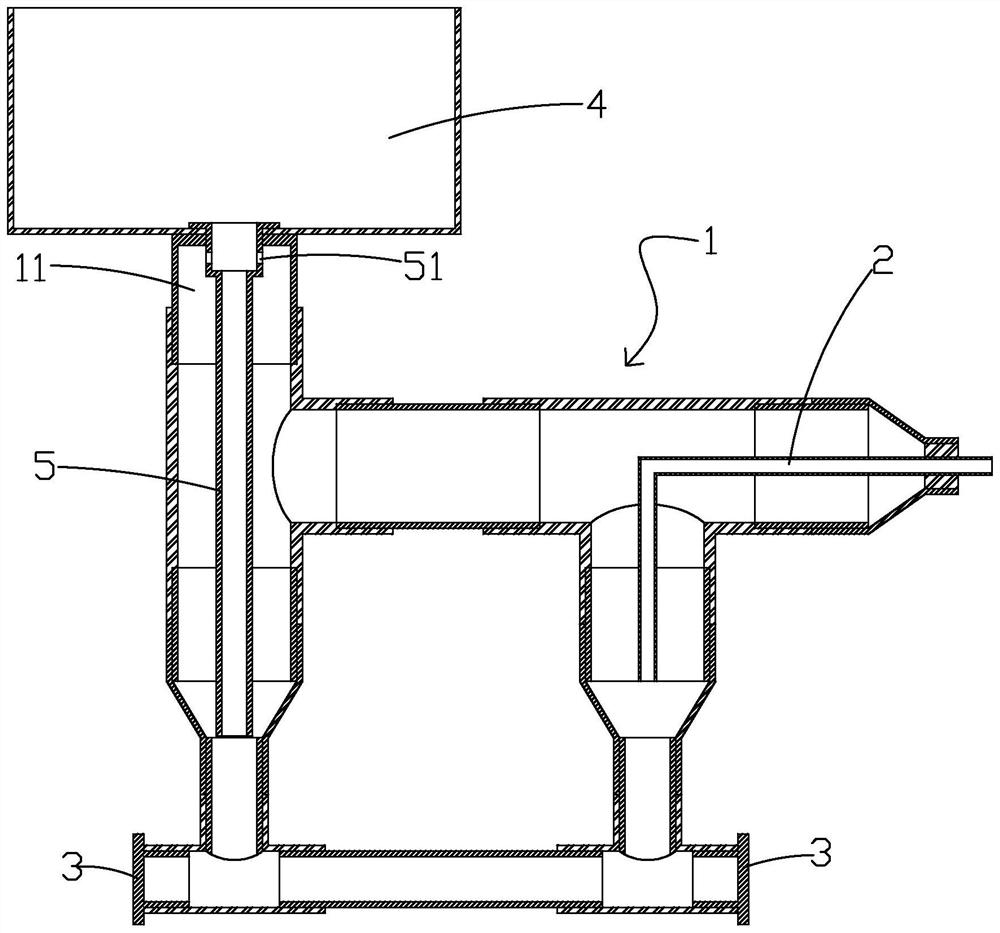
[0029] Please refer to the attached figure 2 The difference between this embodiment and the first embodiment is that a water inlet riser 5 is installed in the side pipe of the water storage pipe main body 1 provided with the water inlet 11, and the upper end of the water inlet riser 5 is connected with the water outlet of the water tank 4. The lower end of the water inlet riser 5 extends toward the bottom of the water storage pipe main body 1 . It can be understood that by installing the water inlet riser 5 in the side pipe of the water storage pipe main body 1 provided with the water inlet 11, the sewage discharged from the water tank 4 can better agitate the water body in the water storage pipe main body 1, The mixing and contact degree of impurities and activated sludge is better, and the decomposition is more sufficient.

[0030] Please refer to the attached figure 2 , a vent hole 41 is opened on the side wall of the water inlet riser 5 near the upper end.


PUM


Abstract

The invention discloses a siphoning type purification blowdown device for a kitchen sink, which comprises a water storage pipe main body, a water inlet communicated with the sink is formed in the top of one side of the water storage pipe main body, a siphoning blowdown pipe is arranged on the other side, far away from the water inlet, of the water storage pipe main body, and the outlet end of the siphoning blowdown pipe laterally penetrates out of the water storage pipe main body in a sealing manner; the installation height of the outlet end of the siphon blow-off pipe is configured to be slightly lower than that of the water inlet in the water storage pipe main body, the inlet end of the siphon blow-off pipe is configured to extend towards the bottom of the water storage pipe main body through bending and has a certain interval distance from the bottom of the water storage pipe main body, and the position, close to the bottom, of the water storage pipe main body is inoculated with activated sludge. The water storage pipe is simple in structure and convenient to mount, and organic matters in sewage can be adsorbed and decomposed through activated sludge in the water storage pipe main body, so that the possibility of blockage of a sewer line is reduced.

Description

technical field [0001] The invention relates to the technical field of purification devices, in particular to a siphon type purification sewage device for kitchen sinks. Background technique [0002] At present, domestic sewage is generally not purified, and is directly discharged into the sewer through simple filtration. On the one hand, this treatment method is still prone to blockage of the sewer, and on the other hand, it will pollute the environment or cause subsequent sewage treatment. cause difficulty. SUMMARY OF THE INVENTION [0003] In view of the deficiencies of the prior art, the present invention provides a siphon-type sewage purification device for a kitchen sink, which mainly solves the problem that the existing domestic sewage is directly discharged into the sewer pipe only through simple filtration, which is still easy to cause the sewer pipe to be blocked. technical problem. [0004] To achieve the above object, the present invention is achieved through...

Claims


Application Information

Patent Timeline
Patent Type & Authority Applications(China)
IPC IPC(8): E03C1/182E03C1/12
CPCE03C1/182E03C1/12E03C2001/1206Y02W10/10
Inventor 刘春嵘杨闻宇
Owner XIAMEN UNIV OF TECH
Learn More