Patient limb supporting and nursing device for radiotherapy department
A nursing device and patient technology, applied in the medical field, can solve the problems of consuming the physical strength of medical staff and patients' family members, not being able to exercise multiple parts of the joints synchronously, and inconvenient handling and carrying, so as to achieve convenient handling and portability and improve back comfort degree, the effect of reducing the degree of fatigue
- Summary
- Abstract
- Description
- Claims
- Application Information
AI Technical Summary
Problems solved by technology
Method used
Image
Examples
Embodiment 1
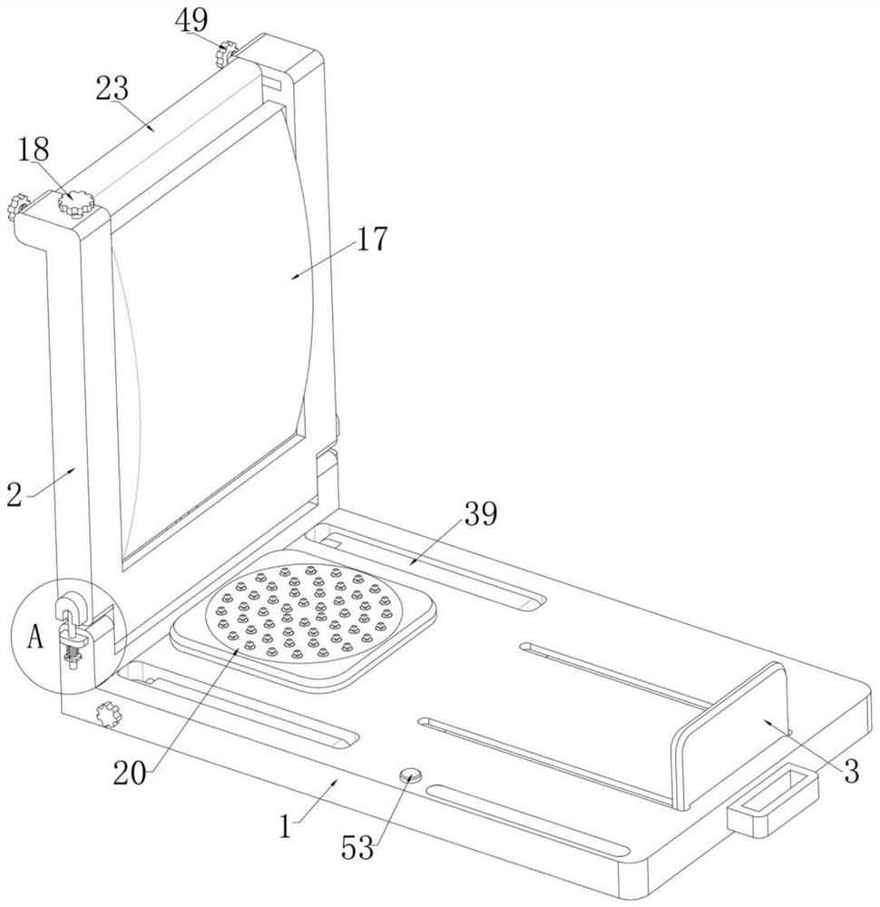
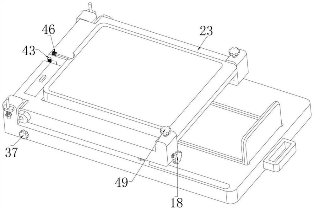
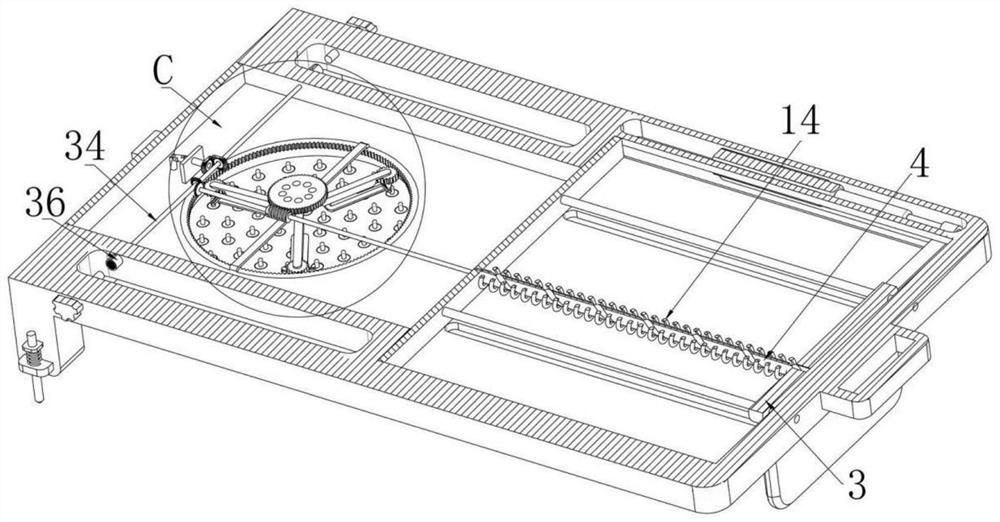
[0040] Example one, as Figure 1-17 As shown in the figure, a patient's limb support and nursing device for radiotherapy includes a base 1, the left and right ends of the base 1 are respectively provided with a left cavity and a right cavity, and the left end of the base 1 is rotatably installed with a The backing plate 2, the backing plate 2 can be folded on the base 1, the upper end of the right side of the base 1 is slidably installed with a foot push plate 3, and the lower end of the foot push plate 3 has through holes in the left and right directions, so A spherical body is fixedly installed in the through hole, such as image 3 As shown, a threaded rod 4 is rotatably installed between the left and right ends of the right cavity and is threaded in the through hole. The threaded rod 4 is provided with a helical groove with a larger pitch, and the spherical body slides Installed in the spiral groove, when the foot push plate 3 slides left and right along the base 1, the sp...
Embodiment 2
[0045] Embodiment 2, on the basis of Embodiment 1, as Figure 12 , 13 As shown, a U-shaped groove 15 is formed on the backing plate 2, a bearing bin 16 is formed at the bottom of the backing plate 2, and an airbag 17 is slidably installed in the U-shaped groove 15. In the initial state, the airbag 17 can be compressed in the bearing 16, the front and rear ends of the air bag 17 are respectively fixed with fixing plates, the fixing plates on the rear side are slidably installed on the inner end of the rear side of the backboard 2, and the fixing plates on the front side are slidably installed. It is installed on the inner end of the front side of the backing plate 2 by sliding up and down. The front end of the backing plate 2 is rotatably installed with a vertical adjusting screw 18 that is threadedly mounted on the front fixing plate. There is an air pump 19 connected with the air bag 17, the air pump 19 is an electric air pump, and is connected to the controller and the powe...
Embodiment 3
[0047] Embodiment 3, on the basis of Embodiment 1, as Figure 8 As shown in the figure, a circular hole runs through the upper and lower sides of the fixing table, and the buttocks massage device includes a disc 20 fixedly installed in the circular hole. Each of the buttock massage rods 21 is respectively sleeved with a return spring located under the disc 20, the upper end of each return spring is fixedly installed on the disc 20, and the lower end of each return spring is respectively fixed and installed on the buttocks massager. On the rod 21, an active massage ball 22 located above the buttock massage rod 21 is fixedly installed on the top of each of the buttock massage rods 21, and each active massage ball 22 is made of rubber material, which can improve comfort;
[0048] During use, when each swing ring 11 slides in the rectangular groove with the corresponding sliding plate 10, each horizontal bar and vertical bar will slide upward against the bottom of each buttock mas...
PUM
 Abstract
Description
Claims
Application Information
 - Generate Ideas
- Intellectual Property
- Life Sciences
- Materials
- Tech Scout
- Unparalleled Data Quality
- Higher Quality Content
- 60% Fewer Hallucinations
Browse by: Latest US Patents, China's latest patents, Technical Efficacy Thesaurus, Application Domain, Technology Topic, Popular Technical Reports.
© 2025 PatSnap. All rights reserved.Legal|Privacy policy|Modern Slavery Act Transparency Statement|Sitemap|About US| Contact US: help@patsnap.com


