
Vehicle-mounted millimeter wave radar

A millimeter-wave radar and housing technology, applied in the field of sensors, can solve the problems such as the inability to effectively meet the lightweight design requirements, the large size of the vehicle-mounted millimeter-wave radar casing, and the increase of the vehicle-mounted millimeter-wave radar process, etc., to achieve high assembly efficiency, The effect of reducing installation cost and easy installation

Pending Publication Date: 2022-06-21
江苏昆文汽车电子技术有限公司
View PDF1 Cites 1 Cited by
  • Summary
  • Abstract
  • Description
  • Claims
  • Application Information

AI Technical Summary

Problems solved by technology

[0002] When assembling traditional vehicle-mounted millimeter-wave radars, the base, shielding parts, and PCB must first be installed in the traditional vehicle-mounted millimeter-wave radars in sequence. Among them, the heat dissipation shielding parts are usually installed in the shell separately by metal die-casting process. , large size, and requires secondary assembly, that is, it needs to be assembled with the shell, base and other components. The installation of the PCB board needs to be fixed with the base in the radar shell through a separate process, which not only increases the assembly of the vehicle-mounted millimeter-wave radar In addition, due to the overlap and avoidance of the parts, the size of the conventional vehicle-mounted millimeter-wave radar housing is relatively large, which cannot effectively meet the lightweight design requirements.

Method used


Image

  • Vehicle-mounted millimeter wave radar
  • Vehicle-mounted millimeter wave radar
  • Vehicle-mounted millimeter wave radar

Examples

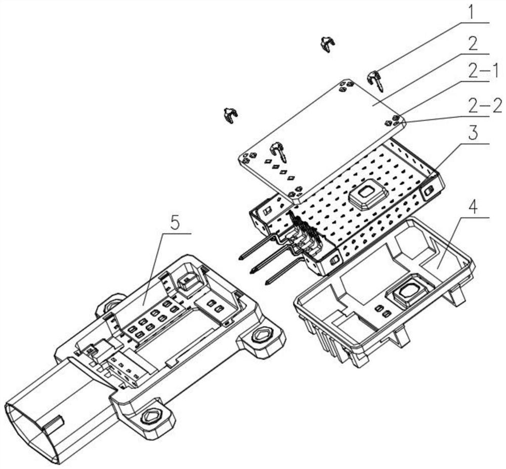
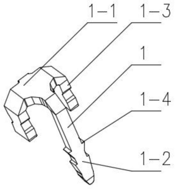
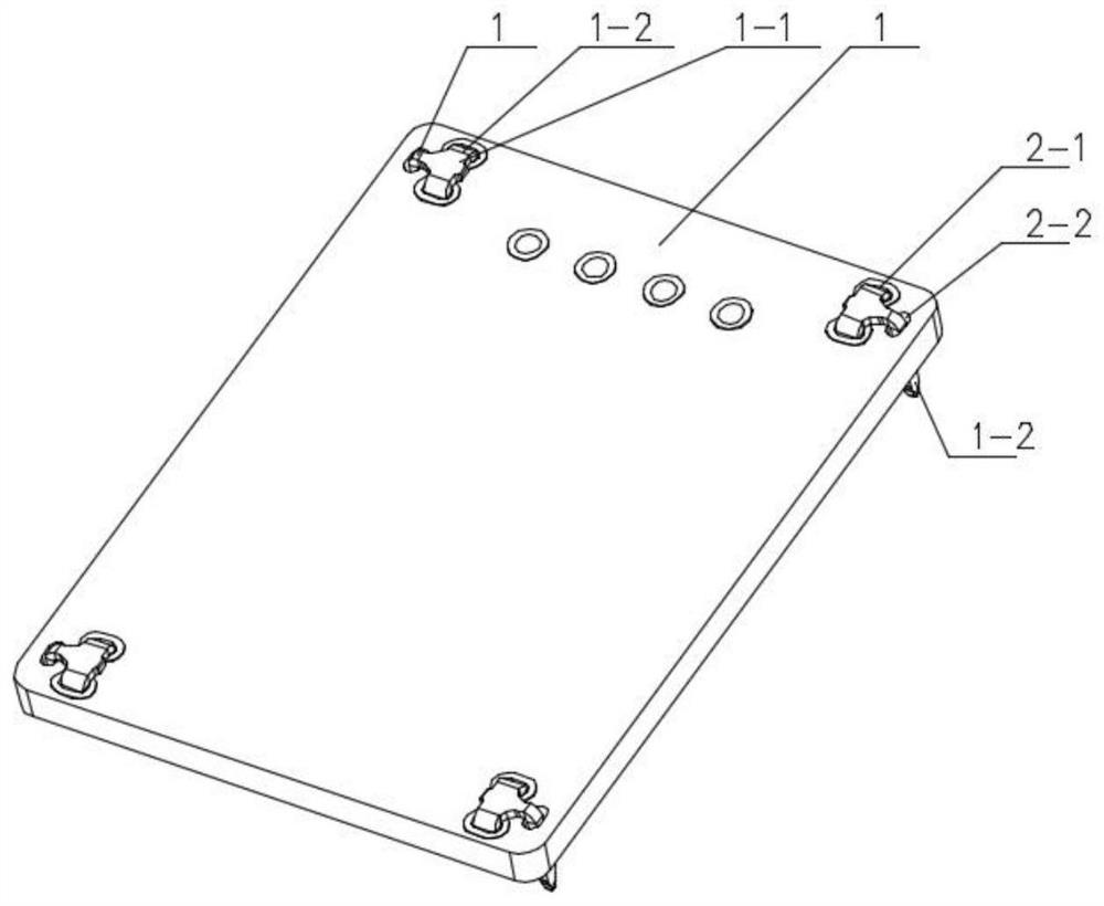

Embodiment Construction

[0025] The present invention will be further described in detail below in conjunction with the accompanying drawings. The following embodiments are only descriptive, not restrictive, and cannot limit the protection scope of the present invention.

[0026] A vehicle-mounted millimeter-wave radar PCB, see figure 1 , Figure 4 , the PCB board 2 in the vehicle-mounted millimeter-wave radar and the base 4 in the vehicle-mounted millimeter-wave radar housing 5 are fixed by a plurality of rivets 1, and an open box-shaped shielding part 3 is installed in the base, and the shielding part is embedded Stamped metal parts in the injection molding cavity of the vehicle-mounted millimeter-wave radar housing.

[0027] The shielding part includes a bottom plate 3-1, the front and rear sides and the left and right sides of the bottom plate are respectively punched upwards with symmetrical front and rear side plates and symmetrical left and right side plates, and the four corners of the bottom...


PUM


Abstract

The invention relates to a vehicle-mounted millimeter-wave radar PCB (printed circuit board), a base is mounted in a vehicle-mounted millimeter-wave radar shell, the PCB in the vehicle-mounted millimeter-wave radar and the base in the vehicle-mounted millimeter-wave radar shell are fixed through a plurality of rivets, and an open box-shaped shielding part is pre-embedded in the vehicle-mounted millimeter-wave radar shell. According to the vehicle-mounted millimeter wave radar, the shielding piece is buried in the radar shell, so that a large amount of space is saved in the shell, PCB installation is facilitated, meanwhile, the size of the shell can be properly reduced, the PCB fixing structure is completed through the rivets, and the cost is reduced. According to the fixing structure, the mounting hole is prefabricated in the PCB, the PCB positioning head and the rivet body of the rivet are coaxially inserted into the mounting hole, so that the relative positions of the rivet and the PCB are fixed, and then the rivet is tapped into the shell base to realize assembly, so that the fixing structure has relatively high assembly efficiency, the manufacturing process of mounting the PCB is simplified, and the production cost is reduced. And meanwhile, certain flexibility is achieved, and the adaptability of the PCB on the fixing point of the shell base is improved.

Description

technical field [0001] The invention belongs to the field of sensors, in particular to a vehicle-mounted millimeter-wave radar. Background technique [0002] When assembling traditional vehicle-mounted millimeter-wave radars, the base, shielding parts, and PCB must first be installed in the traditional vehicle-mounted millimeter-wave radars in sequence. Among them, the heat dissipation shielding parts are usually installed in the shell separately by metal die-casting technology. , large size, and requires secondary assembly at the same time, that is, it needs to be assembled with the shell, base and other components. The installation of the PCB board needs to be fixed with the base in the radar shell through a separate process, which not only increases the assembly of the vehicle-mounted millimeter-wave radar In addition, due to the overlapping and avoidance of the positions of various components, the size of the traditional vehicle-mounted millimeter-wave radar housing is r...

Claims


Application Information

Patent Timeline
IPC IPC(8): H05K7/14H05K7/20H05K9/00H01Q1/42
CPCH05K7/14H05K9/0007H05K7/20H01Q1/42
Inventor 严安姚涛
Owner 江苏昆文汽车电子技术有限公司
Learn More