
Pipe fitting chamfering machine for fitness equipment production and processing

A technology of fitness equipment and chamfering machine, which is applied in metal processing machinery parts, metal processing equipment, manufacturing tools, etc., can solve the problems of poor cooling effect, shorten the service life of chamfering knives, and increase the temperature of chamfering knives, and achieve cooling good effect

Active Publication Date: 2022-06-21
宁波益铸智能科技有限公司
View PDF6 Cites 0 Cited by
  • Summary
  • Abstract
  • Description
  • Claims
  • Application Information

AI Technical Summary

Problems solved by technology

[0003] In the chamfering process of the existing pipe fittings for fitness equipment processing, the chamfering knife will rub against the pipe fittings when chamfering the pipe fittings, so that the temperature of the chamfering knife rises, the chamfering knife is easy to wear, and the service life of the chamfering knife is reduced. However, the existing pipe fitting chamfering machines for production and processing of fitness equipment mainly cool down the chamfering knife by blowing air. Since the hardness of the pipe fittings on the fitness equipment will be different, some materials have relatively large hardness, and some materials have relatively small hardness. Therefore, when the chamfering knife chamfers pipes with different hardness, the speed of the chamfering knife is also different. When the speed of the chamfering knife is slow, the heat generated per unit time is less. A large amount of heat will be generated inside, and the existing wind for cooling the chamfering knife is constant and cannot be adjusted according to the speed of the chamfering knife, so the cooling effect is relatively poor

Method used


Image

  • Pipe fitting chamfering machine for fitness equipment production and processing
  • Pipe fitting chamfering machine for fitness equipment production and processing
  • Pipe fitting chamfering machine for fitness equipment production and processing

Examples


Embodiment Construction

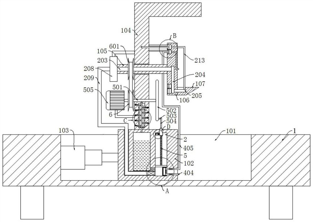
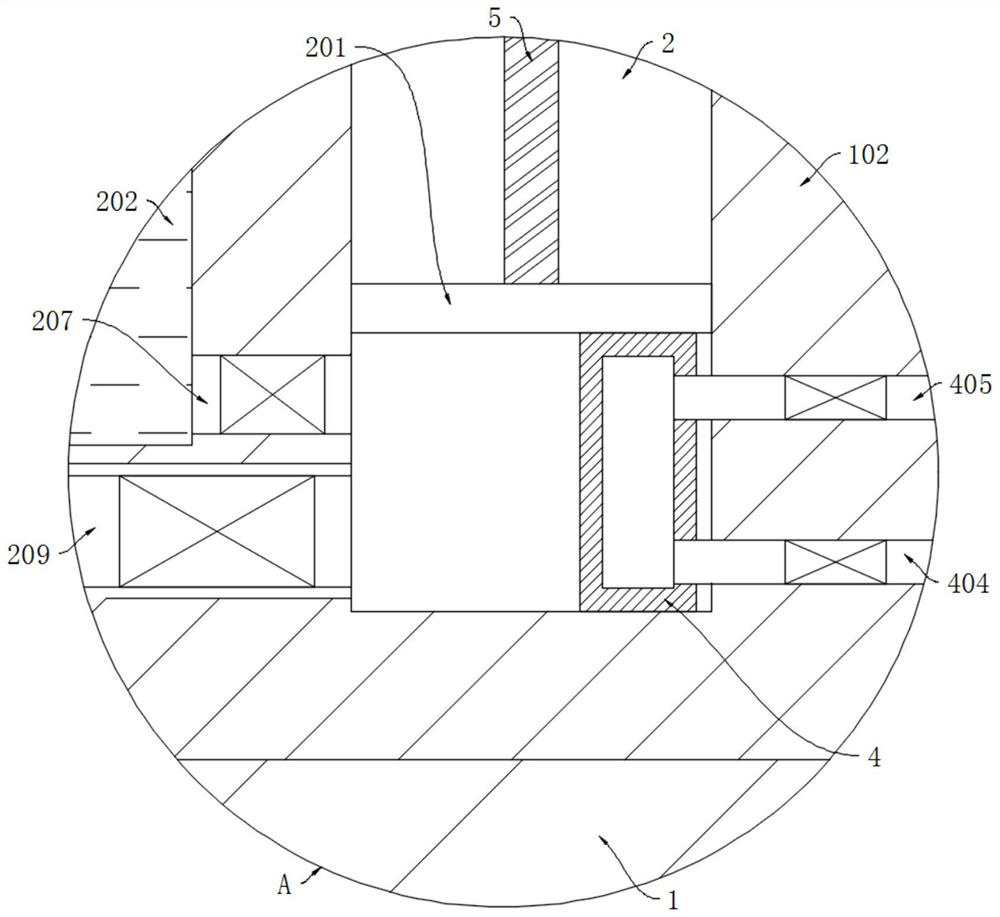
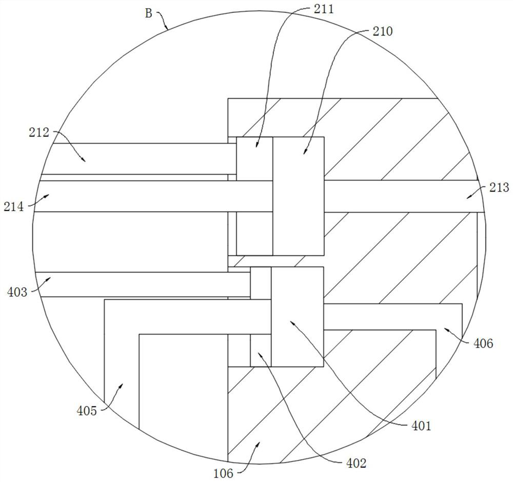
[0024] refer to Figure 1-5 , a pipe fitting chamfering machine for fitness equipment production and processing, comprising a base 1, the lower end of the base 1 is symmetrically and fixedly connected with a support column, and the lower end of the support column is fixedly connected to the ground through expansion screws, the upper end of the base 1 is provided with a chute 101, the chute The inner wall of 101 is slidably connected with a moving block 102, the inner wall of the chute 101 is fixedly connected with an electric push rod 103, the movable end of the electric push rod 103 is fixedly connected with the moving block 102, and the upper end of the moving block 102 is fixedly connected with a mounting rod 104, the mounting rod 104 is L The shape can block the debris generated during the chamfering process, and prevent the debris from flying around and causing injuries to the surrounding workers. The side wall of the mounting rod 104 is rotatably connected to the rotating...


PUM


Abstract

The pipe fitting chamfering machine for fitness equipment production and processing comprises a base, a sliding groove is formed in the upper end of the base, a moving block is slidably connected to the inner wall of the sliding groove, an electric push rod is fixedly connected to the inner wall of the sliding groove, the movable end of the electric push rod is fixedly connected with the moving block, and a mounting rod is fixedly connected to the upper end of the moving block. A rotating shaft is rotatably connected to the side wall of the mounting rod, a mounting plate is fixedly connected to the side wall of the rotating shaft, a chamfering cutter is fixedly connected to the side wall of the mounting plate, a cooling mechanism is mounted on the moving block and comprises a cooling groove and a backflow pipe, the cooling groove is formed in the mounting rod, and the backflow pipe penetrates through the cooling groove. And a cooling mechanism is mounted in the cooling tank. The cooling mechanism can control the amount of the cooling liquid pumped into the chamfering tool according to different rotating speeds of the chamfering tool, cooling can be conveniently conducted according to different heat generated by different rotating speeds of the chamfering tool, and the cooling effect is better.

Description

technical field [0001] The invention relates to the technical field of fitness equipment processing, in particular to a pipe fitting chamfering machine for the production and processing of fitness equipment. Background technique [0002] At present, the country vigorously advocates national fitness and healthy life, and fitness equipment is mainly used to assist people in fitness training. These fitness equipment are mainly processed and combined with different pipe fittings, and these pipe fittings need to be inverted during processing corner treatment. [0003] During the chamfering process of the existing pipe fittings for fitness equipment processing, the chamfering knife will rub against the pipe fitting when chamfering the pipe fitting, so that the temperature of the chamfering knife increases, the chamfering knife is easy to wear, and the service life of the chamfering knife is reduced. The existing pipe fitting chamfering machine for the production and processing of...

Claims


Application Information

Patent Timeline
Patent Type & Authority Applications(China)
IPC IPC(8): B23Q11/10B23Q11/00
CPCB23Q11/10B23Q11/005Y02P70/10
Inventor 孙亚明
Owner 宁波益铸智能科技有限公司
Learn More