Clamping mechanism for steel bar sawing numerical control machine
A technology of clamping mechanism and numerical control machine, which is applied in the direction of clamping, metal processing machinery parts, manufacturing tools, etc., can solve problems such as easy shaking, uneven steel bars, and affecting the cutting accuracy of steel bars, so as to reduce irregular steel bars and reduce The effect of adjusting and improving production efficiency
Active Publication Date: 2022-06-21
江苏中动机械科技有限公司
View PDF8 Cites 0 Cited by
- Summary
- Abstract
- Description
- Claims
- Application Information
AI Technical Summary
Problems solved by technology
[0004] However, as far as the current steel bar CNC cutting machine is concerned, when cutting the steel bar, it is necessary to arrange and fix the steel bar at the cutting position. When the existing steel bar CNC cutting machine advances the steel bar, the material is transported by a roller or a conveyor belt. , it is easy to shake during the transportation process, resulting in uneven cutting of a set of steel bars, thus affecting the accuracy of steel bar cutting
Method used
View moreImage
Smart ImageViewing Examples
Examples
Embodiment
Login to View More PUM
 Abstract
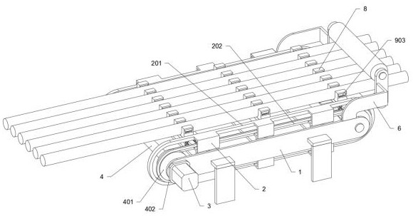
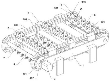
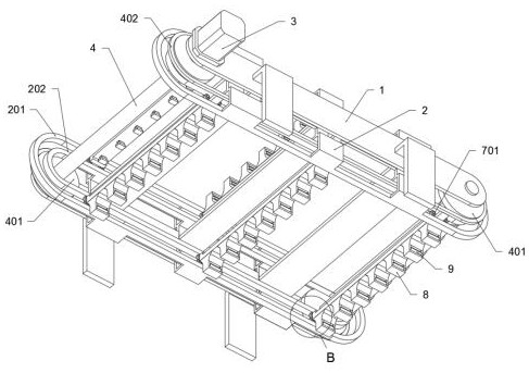
The invention provides a clamping mechanism for a steel bar sawing numerical control machine, and relates to the technical field of machining. An inner circulation guide frame is fixedly connected to the inner surfaces of the outer supporting plates through welding, the inner circulation guide frame comprises a circulation outer rail and a circulation inner rail, the number of the outer supporting plates is two, and the middles of the two outer supporting plates are fixedly connected through a connecting rod; the device has the function of assisting in fixing and pushing cut steel bars, is applied to the middle position of a steel bar feeding mechanism and a steel bar cutting mechanism, clamps and fixes the steel bars through a plurality of groups of steel bar fixing seats, and then assists in transferring the steel bars through a pulling mechanism; and the auxiliary steel bar feeding mechanism assists in fixing and synchronously pushing the cut steel bars, so that the problem that in the pushing process of the steel bars by an existing steel bar numerical control cutting machine, the steel bars are conveyed through a roller or a conveying belt, shaking is likely to happen in the conveying process, a group of cut steel bars are uneven, and the steel bar cutting precision is affected is solved.
Description
technical field [0001] The invention relates to the technical field of machining, in particular to a clamping mechanism for a steel bar sawing numerical control machine. Background technique [0002] At present, in the field of mechanical processing and construction, a large number of steel bars need to be used. In order to meet the needs of steel bar production and processing, it is often necessary to cut steel bars of different lengths. In the existing steel bar cutting equipment, in order to adapt to efficient processing In order to meet the needs of high-precision production and high-precision production, a large number of steel bar processing manufacturers use CNC machines to cut steel bars. It has the functions of automatic feeding, quantitative feeding and automatic transfer of workpieces, which greatly saves manpower and material resources, so it has been widely used. [0003] For example, the patent with the publication number CN201510622984.1 discloses an automatic...
Claims
Login to View More Application Information
Patent Timeline
 Patent Type & Authority Applications(China)
IPC IPC(8): B23Q3/00B23Q7/00
CPCB23Q3/00B23Q7/00
Inventor 赖志勇张伟赖琼霞赖伊莉唐婷
Owner 江苏中动机械科技有限公司
Features
- R&D
- Intellectual Property
- Life Sciences
- Materials
- Tech Scout
- Unparalleled Data Quality
- Higher Quality Content
- 60% Fewer Hallucinations
Learn More Browse by: Latest US Patents, China's latest patents, Technical Efficacy Thesaurus, Application Domain, Technology Topic, Popular Technical Reports.
© 2025 PatSnap. All rights reserved.Legal|Privacy policy|Modern Slavery Act Transparency Statement|Sitemap|About US| Contact US: help@patsnap.com


