Eureka AIR delivers breakthrough ideas for toughest innovation challenges, trusted by R&D personnel around the world.

Comprehensive air inlet device of household garbage incinerator

A technology of domestic waste incineration and air intake device, which is applied in the direction of incinerator, combustion type, combustion method, etc., to achieve good combustion effect

Pending Publication Date: 2022-06-10
詹海文
View PDF0 Cites 0 Cited by
  • Summary
  • Abstract
  • Description
  • Claims
  • Application Information

AI Technical Summary

Problems solved by technology

[0003] In order to solve the above technical problems, the present invention provides a comprehensive air intake device for domestic waste incinerators to solve the problem that the air cannot completely enter the furnace body. It will burn completely, causing the problem that the raw materials inside the furnace body cannot be fully burned. At the same time, when the air enters the furnace, the ash in the furnace will be blown up, which will increase the content of dust and other particulate matter in the smoke.

Method used


Image

  • Comprehensive air inlet device of household garbage incinerator
  • Comprehensive air inlet device of household garbage incinerator
  • Comprehensive air inlet device of household garbage incinerator

Examples


Embodiment 1

[0031] When the air guide tooth 307 enters the air guide groove 317 at the bottom of the retaining wall 302, the opening and closing door 309 in the bottom of the air guide groove 317 will be pushed back, and the top column 310 at the bottom will be opened after the opening and closing door 309 is fully opened and closed. The airtight door 308 at the top of the air guide tooth 307 is pushed open, and the air will enter the inside of the retaining wall 302 through the air guide tooth 307 at this time.

[0032] Embodiment three:

[0033] When the air deflector 311 moves upward, the connecting column 315 will be used to drive the combustion-supporting plate 314 to move upward along the movable groove 312 .

Embodiment 2

[0035]When the combustion-supporting plate 314 moves to the top of the movable groove 312, the material dial column 318 on the top of the combustion-supporting plate 314 will protrude through the hole in the combustion net 313, and the raw material will be pushed and exchanged so that the raw material can be fully burned, and the combustion-supporting plate 314 will The one-way valve 318 on the board is opened, and the dust collected on the board is introduced into the collection drawer 4 .

[0036] Embodiment five:

[0037] When the combustion-supporting plate 314 moved to the bottom of the movable groove 312, the one-way valve 318 on the plate was closed, so that the flame-retardant plate 314 formed a sealed plate, and the ashes on the conveyor belt 301 were sucked on the conveyor belt 301 by the holes in the combustion net 313. Burner plate 314.

Embodiment 3

[0039] When the transmission shaft 106 rotates, it will drive the drive shaft 305 to rotate and make the conveyor belt 301 meshed with it rotate. At this time, the drive shaft 305 will input air into the interior through the transmission shaft 106, and the imported air will enter the air guide teeth 307. When the guide When the gas tooth 307 enters the air guide groove 317 at the bottom of the retaining wall 302, the opening and closing door 309 in the bottom of the air guiding groove 317 will be pushed back, and the top column 310 at the bottom will guide the air after the opening and closing door 309 is fully opened and closed. The airtight door 308 on the top of the teeth 307 is pushed back, and now the air will enter the inside of the retaining wall 302 through the air guide teeth 307 and blow up the air deflector 311 to guide the air out of the surface of the conveyor belt 301 so that the raw materials can be fully burned.

[0040] When the air deflector 311 moves upwards,...


PUM


Abstract

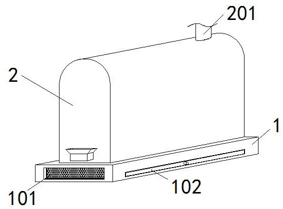
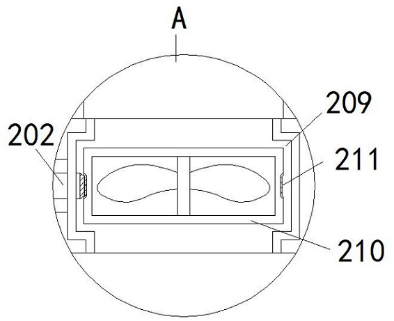
The comprehensive air inlet device of the household garbage incinerator comprises a base, an incinerator body, an air inlet grate and a collecting drawer, the incinerator body is fixedly connected to the top end of the base, a smoke exhaust pipe is fixedly connected to the top of the incinerator body, a transmission shaft is connected to the inner wall of the top of the incinerator body through a bearing, and a driving shaft is connected to the side wall of the incinerator body through a bearing; an air inlet is formed in the inner wall of the left side of the base, an opening is formed in the inner wall of the front face of the base, the collecting drawer is movably connected into the opening, the air inlet grate is embedded into the base, and the collecting drawer is located in the center of the air inlet grate; according to the comprehensive air inlet device of the household garbage incinerator, the problem that raw materials in the incinerator body cannot be fully combusted due to the fact that air cannot completely enter the incinerator body and the air is burnt up at the front end is solved, meanwhile, furnace ash in the incinerator is blown up during air inlet, and the combustion efficiency is improved. And the content of particulate matters such as dust in the smoke is increased.

Description

technical field [0001] The invention relates to the technical field of garbage incinerators, in particular to a comprehensive air inlet device for domestic garbage incinerators. Background technique [0002] The air intake device is directly related to whether the combustion is normal or not. No matter what kind of cooker it is, the damper must be adjusted properly. If the damper is too large, the air volume will be too much, and the fire will not be easy to ignite. Entering the interior of the furnace body, the ashes in the furnace are blown up and mixed into the smoke, which increases the impurity content in the smoke and increases unnecessary workload for the purification equipment. Contents of the invention [0003] In order to solve the above technical problems, the present invention provides a comprehensive air intake device for domestic waste incinerators to solve the problem that the air cannot completely enter the furnace body and the air will burn out at the fron...

Claims


Application Information

Patent Timeline
Patent Type & Authority Applications(China)
IPC IPC(8): F23G5/00F23G5/44
CPCF23G5/00F23G5/44
Inventor 詹海文
Owner 詹海文
Why Eureka
Eureka Blog
Learn More