Ultrasonic quilting machine
An ultrasonic, quilting technology used in textiles and papermaking, application, cutting of textile materials, etc.
Pending Publication Date: 2022-06-10
上工富怡智能制造(天津)有限公司
View PDF0 Cites 1 Cited by
- Summary
- Abstract
- Description
- Claims
- Application Information
AI Technical Summary
Problems solved by technology
[0002]The existing ultrasonic quilting can not achieve the effect of welding joints on both sides, in order to better meet the customer's use requirements
Method used
View moreImage
Smart ImageViewing Examples
Examples
Embodiment Construction
Login to View More PUM
 Abstract
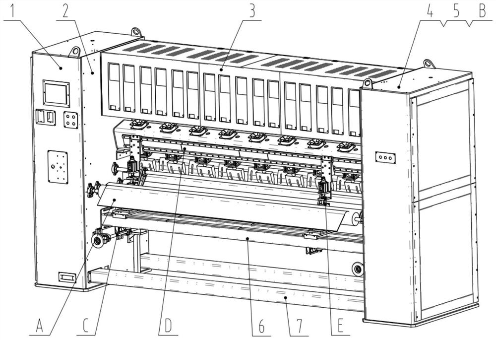
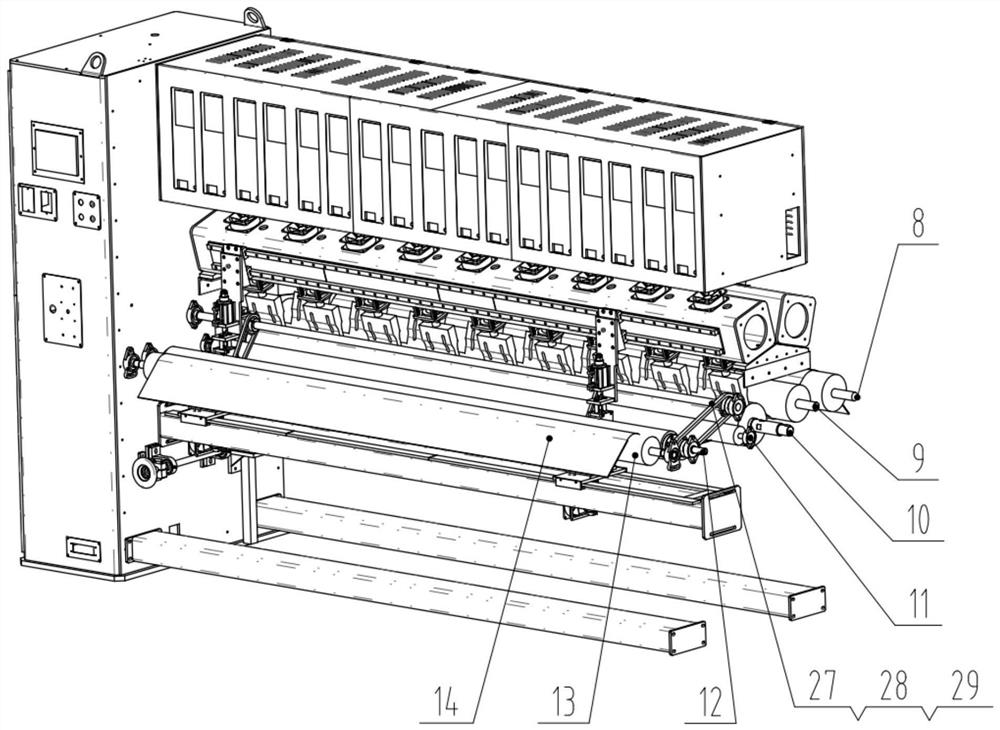
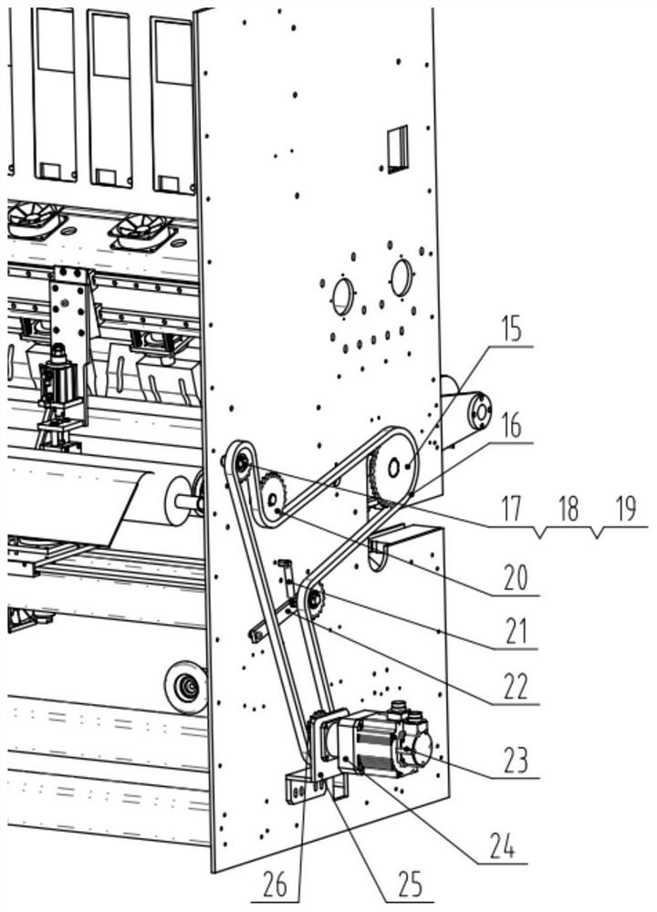
The invention discloses an ultrasonic quilting main machine which comprises a left side box body, a left side plate, a generator support, a right side plate, a right side box body, an edge cutting ultrasonic fixed sliding rail, a fixed lower beam, a cloth trend, a transmission part, a flower roller adjusting part, an ultrasonic part, an edge cutting part and a centrifugal fan. Cloth penetrates in from the upper portion of the first scutching roller from the rear portion from bottom to top, passes through the lower portion of the second scutching roller, the upper portion of the ultrasonic embossing roller, the lower portion of the cloth passing roller, the position between the edge cutting embossing wheel and the second ultrasonic welding head and the position below the first cloth outlet rubber coating roller, and finally penetrates out from the position between the first cloth outlet rubber coating roller and the second cloth outlet rubber coating roller. According to the invention, the use requirement of customers on the edge-cutting welding spots of the cloth finished products is met, and the widths of different cloth finished products are realized by adjusting the position of the edge-cutting part on the guide rail sliding block and the position of the ultrasonic mounting plate II on the edge-cutting ultrasonic fixed sliding rail; and the replacement of the ultrasonic embossing roller is realized by virtue of an auxiliary part, namely the embossing roller replacement support, so that the requirements of different patterns are met.
Description
technical field [0001] The invention belongs to the technical field of ultrasonic quilting, and belongs to a part of an ultrasonic quilting production line, in particular to an ultrasonic quilting host part. Background technique [0002] The existing ultrasonic quilting can not achieve the effect of cutting and welding joints on both sides, in order to better meet the customer's use requirements. This paper describes an ultrasonic quilting machine, which realizes the effect of side cutting with the main machine and welding spots on the cutting edge of the fabric. Contents of the invention [0003] The purpose of the present invention is to overcome the disadvantages of the above-mentioned prior art, and provide an ultrasonic quilting main machine, which can achieve the effect that both sides of the normal quilting of the ultrasonic main machine are accompanied by trimming, and the cloth is cut with welding spots . [0004] Ultrasonic quilting host, including: left box, l...
Claims
Login to View More Application Information
Patent Timeline
 Patent Type & Authority Applications(China)
IPC IPC(8): B29C65/74B29C65/08D06H7/06D06C23/00
CPCB29C65/74B29C65/08D06H7/06D06C23/00B29L2031/726
Inventor 刘金海谢肖飞
Owner 上工富怡智能制造(天津)有限公司
- R&D Engineer
- R&D Manager
- IP Professional
- Industry Leading Data Capabilities
- Powerful AI technology
- Patent DNA Extraction
Learn More Browse by: Latest US Patents, China's latest patents, Technical Efficacy Thesaurus, Application Domain, Technology Topic, Popular Technical Reports.
© 2024 PatSnap. All rights reserved.Legal|Privacy policy|Modern Slavery Act Transparency Statement|Sitemap|About US| Contact US: help@patsnap.com


