
Optical disc device and data reading method

An optical disc device and data reading technology, applied in data recording, digital recording/reproduction, digital signal error detection/correction, etc., can solve the problem of arranging code data blocks of 64K bytes or more user data and reduce coding Efficiency, increased redundancy, etc.

Inactive Publication Date: 2004-04-14
SONY CORP
View PDF0 Cites 0 Cited by
  • Summary
  • Abstract
  • Description
  • Claims
  • Application Information

AI Technical Summary

Problems solved by technology

However, in RS (Reed-Solomon) codes employing general GF(2^8), it is difficult to arrange code data blocks having 64K bytes or more of user data, unlike typical DVDs using PRC
[0012] Although it is desirable to increase the capacity of the disc as much as possible, it is not desirable to significantly reduce coding efficiency and increase redundancy

Method used


Image

  • Optical disc device and data reading method
  • Optical disc device and data reading method
  • Optical disc device and data reading method

Examples


Embodiment Construction

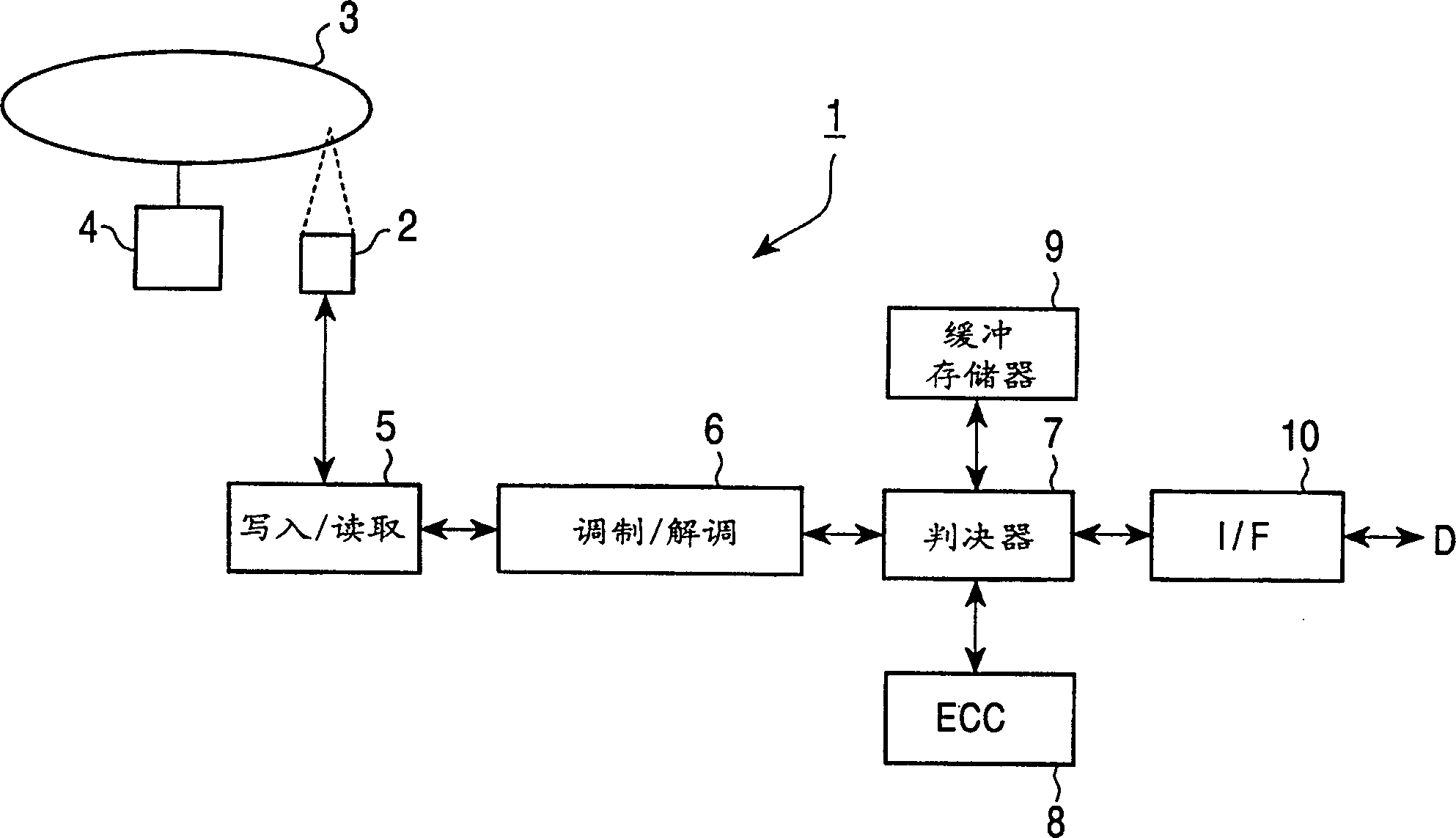
[0026] like figure 1 As shown, an optical disc device 1 writes user data D1 sequentially input from an external device such as a computer to an optical disc 3 through an interface (I / F) 10 by means of an optical pickup 2 having a high numerical aperture.

[0027] The device 1 reads data recorded on the optical disc 3, and outputs the data through the I / F10. The optical disc 3 is obtained by laminating a transparent disc substrate, an information recording surface and a rear protective substrate so that the entire thickness of the optical disc 3 is set to 1.2mm, and the transparent disc substrate The thickness is 0.1mm. The transparent disc substrate is designed to allow the laser beam emitted from the optical pickup 2 to pass therethrough so that the light is incident on the information recording surface. By setting the numerical aperture (NA) of the optical pickup 2 to a high value, the optical disc 3 is allowed to reduce the influence due to skew even though information i...


PUM


Abstract

An optical disk apparatus reads data written in an optical disk in units of code blocks arranged by joining a plurality of correcting codes. The optical disk apparatus includes a reading unit for reading the code block from the optical disk and an error correcting unit for combining first error correcting processing performed on the code block read by the reading unit with second error correcting processing performed by adding remove information to codes that cannot be corrected during at least the first error correcting processing.

Description

technical field [0001] The present invention relates to an optical disc device which reads data in units of code data blocks arranged by connecting a plurality of error correction codes from an optical disc. Background technique [0002] In the past, in an optical disc device that reads information from and writes information to an optical disc, the bit error rate of user data has been improved sufficiently for practical use by means of a predetermined error correction code. Figure 8 Indicates that the disc sector format is determined by the International Organization for Standardization (ISO). exist Figure 8 In , only the relationship between user data and error correction codes is shown, and address cells, voids, VFO (Variable Frequency Oscillator), synchronization signals, etc. are omitted. This optical disc device arranges data blocks of user data input successively, forms ECC (Error Correction Code) by adding error correction codes to the arranged data blocks based on...

Claims


Application Information

Patent Timeline
IPC IPC(8): H04N5/85G11B20/18G11C29/00H03M13/29H04N5/92H04N5/926
CPCH03M13/293H03M13/3746G11B20/1866H03M13/2909H04N5/85G11B20/1833H03M13/2707G11B2220/2562H03M13/373G11B2020/1853G11B2020/1836H04N9/888H03M13/1515G11B20/18
Inventor 千秋进
Owner SONY CORP
Learn More