
Control circuit for heater with variable resistance associated with sensor for detecting oxygen in exhaust gases

A control circuit and oxygen sensor technology, applied in electrical control, non-electric variable control, temperature control, etc., can solve problems such as power dissipation, heater efficiency loss, and error increase

Inactive Publication Date: 2004-04-14
STMICROELECTRONICS SRL +1
View PDF0 Cites 0 Cited by
  • Summary
  • Abstract
  • Description
  • Claims
  • Application Information

AI Technical Summary

Problems solved by technology

However, in steady state, when the current is low, the voltage drop across the measurement resistor with low resistance is only a few millivolts (mv), resulting in large measurement errors and due to the non-negligible offset compared to the useful signal and drift also increases the error
[0006] On the other hand, the use of a measuring resistor with a high resistance value will produce a loss of efficiency of the heater in the phase immediately following start-up (it will take longer to reach a steady state), especially during the initial phase. Produces large power dissipation with significant size issues

Method used


Image

  • Control circuit for heater with variable resistance associated with sensor for detecting oxygen in exhaust gases
  • Control circuit for heater with variable resistance associated with sensor for detecting oxygen in exhaust gases
  • Control circuit for heater with variable resistance associated with sensor for detecting oxygen in exhaust gases

Examples


Embodiment Construction

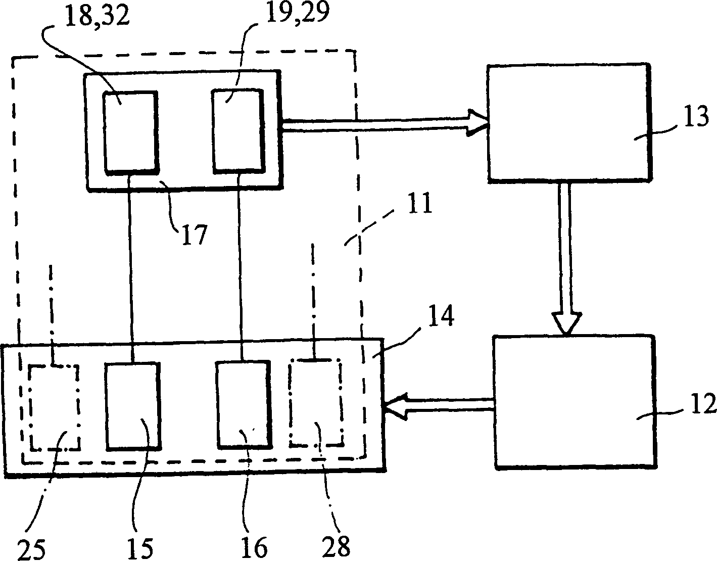
[0028] figure 1 A system 11 for controlling emissions from an internal combustion engine 12 of a vehicle is represented in block diagram form.

[0029] This system 11 works in conjunction with a fuel injection system 13 and a catalytic converter 14 . It comprises: a sensor 15 (lambda probe) for detecting oxygen in the exhaust gas associated with an electric heater 16 ; and an electronic control unit 17 . A microprocessor 18 is included.

[0030] The lambda probe 15 can provide a signal indicative of the oxygen content in the exhaust gas.

[0031] The electronic unit 17 uses these signals to adjust the injection system 13 to achieve the optimum air-oil ratio.

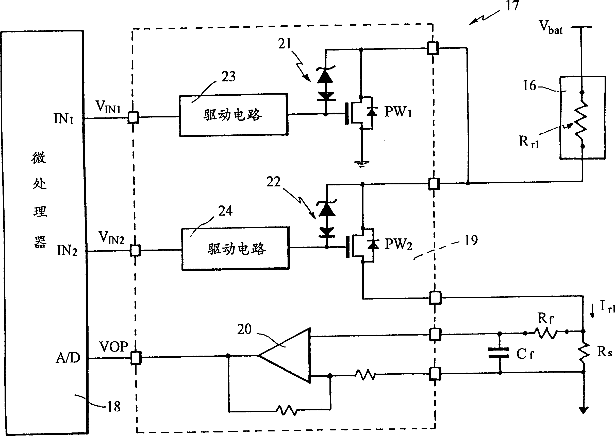
[0032] The probe 15 is installed in the converter 14 together with an electric heater. This heater consists of a resistor R r1 (See image 3 ), whose first terminal is connected to one terminal of a DC voltage source, such as the positive terminal of a car battery.

[0033] The electronic unit 17 includes a contro...


PUM


Abstract

A circuit comprises a measurement resistor (Rs) in series with a heater (16, 18); a detector circuit (20) for providing a signal (VOP) indicative of the current flowing in the resistor (Rs); switching devices (PW1, PW2, PW3, PW4) for controlling the connection of the heater (16, 28) to a voltage source (Vbat) and the connection of the measurement resistor in the supply circuit comprising the source (Vbat) and the heater (16, 28); and a control unit (18, 32) arranged to drive the switching devices in a manner such that each time the heater (16, 28) is activated, the measurement resistor (Rs) is kept disconnected from the supply circuit of the heater (16, 28) for a predetermined period of time and the measurement resistor (Rs) is then connected in the supply circuit of the heater (16, 28).

Description

technical field [0001] The invention relates to a control circuit for a heater with a variable resistor connected to a sensor for detecting the oxygen content of the exhaust gas, in particular for an internal combustion engine of a motor vehicle. Background technique [0002] Current O.B.D. II standards for emissions (exhaust) require that the operating temperature of the lambda probes be kept within well defined limits. This requirement cannot be met simply by selecting the resistance value of the heater and / or by its automatic compensation. [0003] The functionality of the heater can be monitored by accurately detecting the current flowing through a measuring resistor connected to the heater and, if desired, the functionality of the probe for subsequent adjustment operations can be deduced therefrom. [0004] Given the tight tolerances imposed by the O.BD.II standard, this current measurement must be very precise, which contradicts two opposing requirements for the resis...

Claims


Application Information

Patent Timeline
Patent Type & Authority Patents(China)
IPC IPC(8): F02D41/14
CPCF02D41/1494
Inventor V·乔治塔P·马斯特勒G·马治奥尼M·康图西
Owner STMICROELECTRONICS SRL
Learn More