A thin slice laser crystal cooling device and laser

A laser crystal and cooling device technology, applied in laser cooling devices, lasers, laser parts, etc., can solve the unreasonable integration of thin-film laser crystal thermal management, the inability to achieve efficient thermal management of thin-film laser crystals, and the thermal management of thin-film laser crystals. Unreasonable way and other problems, to achieve the effect of novel and simple structure, improve service life, and release thermal stress

Active Publication Date: 2022-08-05
INST OF APPLIED ELECTRONICS CHINA ACAD OF ENG PHYSICS
View PDF7 Cites 0 Cited by
  • Summary
  • Abstract
  • Description
  • Claims
  • Application Information

AI Technical Summary

Problems solved by technology

[0003] In the existing thin-chip lasers, the thermal management method of the thin-chip laser crystal is unreasonable and cannot meet the requirements of efficient cooling. At the same time, the thermal management integration method of the thin-chip laser crystal is unreasonable. On the one hand, it cannot meet the requirements of stress release in the work of thin-film laser crystals, which will easily lead to the failure of efficient thermal management of thin-film laser crystals, and the ineffective release of working stress, which will affect the normal operation of thin-film laser crystals.

Method used


Image

  • A thin slice laser crystal cooling device and laser
  • A thin slice laser crystal cooling device and laser
  • A thin slice laser crystal cooling device and laser

Examples


Embodiment 1

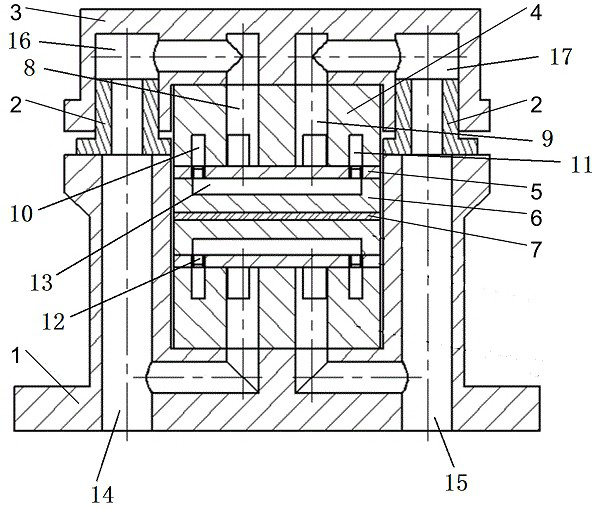
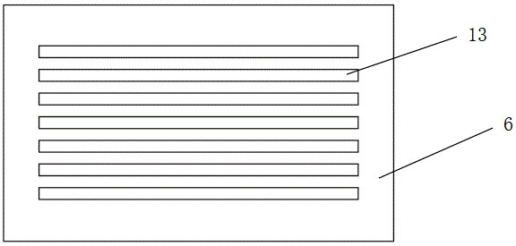
[0048] like Figure 1-Figure 3 As shown, a thin-film laser crystal cooling device includes a liquid inlet and outlet plate 4, a liquid separation plate 5 and a direct cooling plate 6 in turn. The liquid inlet and outlet plate 4 is provided with a liquid inlet 8 and a liquid return port 9. The liquid plate 5 is provided with a liquid separation through hole 12, one side of the direct cooling plate 6 is attached to the thin laser crystal 7, and the other side is provided with a cooling groove 13, and the cooling groove 13 is passed through the liquid separation. The holes 12 are communicated with the liquid inlet 8 and the liquid return port 9 respectively.

[0049] The liquid inlet 8 and the liquid return port 9 are located on one side of the liquid inlet and outlet plate 4 , and the other side of the liquid inlet and outlet plate 4 is provided with a first fan-shaped structure and a second fan-shaped structure. The first fan-shaped structure corresponds to and communicates wi...


PUM


Abstract

The invention relates to a thin-film laser crystal cooling device and a laser, belonging to the technical field of laser heat dissipation. The thin-film laser crystal cooling device sequentially includes a liquid inlet and outlet plate, a liquid separation plate and a direct cooling plate, and the liquid inlet and outlet plate is provided with a liquid inlet and a liquid inlet and outlet. The liquid return port, the liquid separation plate is provided with a liquid separation through hole, one side of the direct cooling plate is attached to the thin laser crystal, and the other side is provided with a cooling groove, and the cooling groove passes the liquid separation The through holes are respectively connected with the liquid inlet and the liquid return port. The invention can ensure that the cooling liquid is reasonably distributed to the width direction and the length direction of the thin laser crystal, improves the cooling uniformity of the thin laser crystal, and ensures the normal operation of the thin laser crystal. At the same time, compact integration can be realized, the thermal stress of the thin-film laser crystal can be effectively released, and the service life of the thin-film laser crystal can be improved.

Description

technical field [0001] The invention belongs to the technical field of laser heat dissipation, and in particular relates to a thin-film laser crystal cooling device and a laser. Background technique [0002] Thin-film lasers are a class of potential high-power lasers, and the thickness of thin-film laser crystals is generally on the order of millimeters. In the thin slice laser crystal module integrated system, not only the thin slice laser crystal needs to be efficiently cooled, precisely positioned, and compactly integrated, but also the requirements for stress release during the operation of the thin slice laser crystal must be met to ensure the working performance of the thin slice laser system. [0003] In the existing thin-film lasers, the thermal management method of thin-film laser crystals is unreasonable and cannot meet the requirements of efficient cooling. At the same time, the thermal management integration method of thin-film laser crystals is unreasonable. On...

Claims


Application Information

Patent Timeline
Patent Type & Authority Patents(China)
IPC IPC(8): H01S3/04H01S3/042
CPCH01S3/0407H01S3/042
Inventor 陈小明石勇罗兴旺叶峻芝张旭光张雷高清松尚建力鲁燕华张卫万敏唐淳
Owner INST OF APPLIED ELECTRONICS CHINA ACAD OF ENG PHYSICS
Why Eureka
Try Eureka