Optical fiber temperature sensor calibration method and device and computer equipment

An optical fiber temperature and sensor technology, applied in the field of optical fiber sensing, can solve problems such as inconvenient on-site operation, save workload, simplify calibration operation process, and improve calibration efficiency.

Active Publication Date: 2022-06-03
SUZHOU GUANGGE EQUIP
View PDF7 Cites 0 Cited by
  • Summary
  • Abstract
  • Description
  • Claims
  • Application Information

AI Technical Summary

Problems solved by technology

[0003] In related technologies, it is usually calibrated to measure a certain temperature difference in optical fiber manufacturing, requiring staff to carry a high-temperature heat source for calibration, and for links with more loss points, segmental calibration is required, which is very inconvenient for on-site operation

Method used


Image

  • Optical fiber temperature sensor calibration method and device and computer equipment
  • Optical fiber temperature sensor calibration method and device and computer equipment
  • Optical fiber temperature sensor calibration method and device and computer equipment

Examples


Embodiment Construction

[0024] In order to make the objectives, technical solutions and advantages of the embodiments of the present disclosure more clear, the embodiments of the present disclosure will be described in further detail below with reference to the accompanying drawings and the embodiments. It should be understood that the specific embodiments described herein are only used to explain the embodiments of the present disclosure, and are not used to limit the embodiments of the present disclosure.

[0025] In order to facilitate those skilled in the art to understand the technical solutions provided by the embodiments of the present disclosure, the background technology for implementing the technical solutions is first described below.

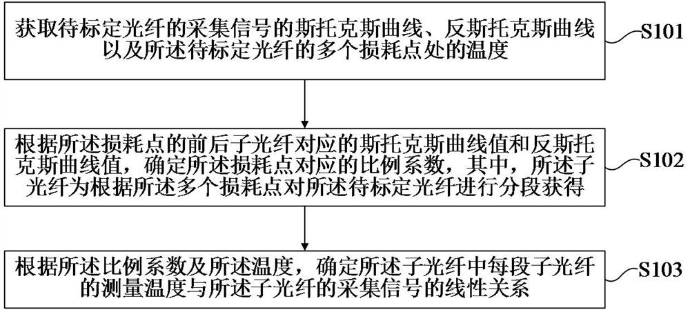
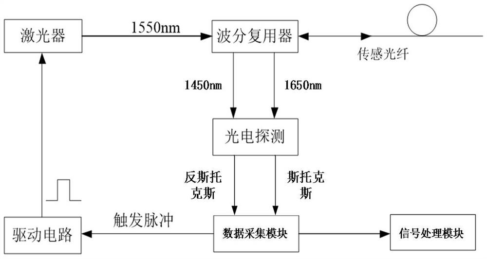
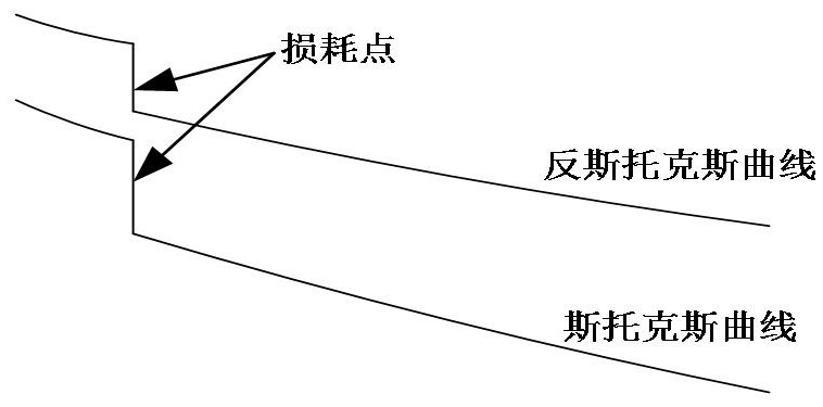
[0026] In the distributed optical fiber temperature sensor, when demodulating the temperature by the collected stokes (Stokes light) and anti-stokes (anti-Stokes light) light intensity values, the ratio is taken. -stokes attenuation difference, its principl...


PUM


Abstract

The embodiment of the invention relates to an optical fiber temperature sensor calibration method and device, computer equipment, a storage medium and a computer program product. The method comprises the following steps: acquiring a Stokes curve and an anti-Stokes curve of an acquisition signal of a to-be-calibrated optical fiber and temperatures at a plurality of loss points of the to-be-calibrated optical fiber; according to Stokes curve values and anti-Stokes curve values corresponding to front and rear sub-optical fibers of the loss point, a proportionality coefficient corresponding to the loss point is determined, and the sub-optical fibers are obtained by segmenting the optical fiber to be calibrated according to the plurality of loss points; and according to the proportionality coefficient and the temperature, determining a linear relationship between the measured temperature of each section of sub-optical fiber in the sub-optical fibers and the collected signal of the sub-optical fiber. The method can simplify the calibration operation process of the optical fiber temperature sensor, saves the workload, and improves the calibration efficiency.

Description

technical field [0001] The embodiments of the present disclosure relate to the technical field of optical fiber sensing, and in particular, to a method, apparatus, computer equipment, storage medium, and computer program product for calibrating an optical fiber temperature sensor. Background technique [0002] Distributed optical fiber temperature sensor is a kind of optical fiber sensor system for real-time measurement of spatial temperature field distribution. It has the characteristics of intrinsic passive, anti-electromagnetic interference, continuous linear temperature measurement, corrosion resistance, easy installation and integration, etc. Online real-time temperature monitoring and early warning and alarm of fire, gas and liquid leakage in cables, tunnels, coal mines, oil wells and other fields. However, before using the distributed fiber optic temperature sensor in the specific application scenario, it needs to be calibrated, that is, according to the function rela...

Claims


Application Information

Patent Timeline
IPC IPC(8): G01K15/00
CPCG01K15/005
Inventor 郎国伟陈科新张超
Owner SUZHOU GUANGGE EQUIP
Why Eureka
Try Eureka