Wall structure detection device for old community reconstruction planning

A technology of wall structure and detection device, which is applied in the direction of sampling device, material inspection product, mechanical thickness measurement, etc., can solve the problems of staff interference, impact of drill pipe, and low service life, so as to improve structural stability and avoid detection Error, the effect of improving the service life

Pending Publication Date: 2022-06-03
湖南城市学院设计研究院有限公司
View PDF8 Cites 0 Cited by
  • Summary
  • Abstract
  • Description
  • Claims
  • Application Information

AI Technical Summary

Problems solved by technology

[0002] When planning and renovating the community, the first choice is to inspect the wall structure. It is necessary to sample the wall and measure the thickness of each layer of the wall. The existing sampling equipment will form a gap between the drill pipe and the sampling hole when sampling, and During the drilling process of the drill pipe, the gas will be poured into the sampling hole and the dust will be brought out, and the dust will fall down along the wall, causing interference to the staff at the lower part of the wall, and will also affect the health of the equipment operators. ;
[0003] Moreover, the existing sampling equipment either does not have a cutting device, or sets a cutting tooth in the drill rod. The cutting tooth is in the shape of a ratchet. The teeth extend out to cut off the sample, but the cut-off teeth are fixed by the pin shaft, and stress concentration is easily formed during the cut-off work, and due to high-speed rotation, the clockwise stress will be very large, which will not only break the pin shaft, but also further damage the drill pipe. As a result, the service life of the equipment is low, and cutting teeth need to be set, the structure is complicated, the production cost and the subsequent maintenance cost increase significantly, which is not conducive to the popularization and use of the equipment

Method used


Image

  • Wall structure detection device for old community reconstruction planning
  • Wall structure detection device for old community reconstruction planning
  • Wall structure detection device for old community reconstruction planning

Examples


Embodiment

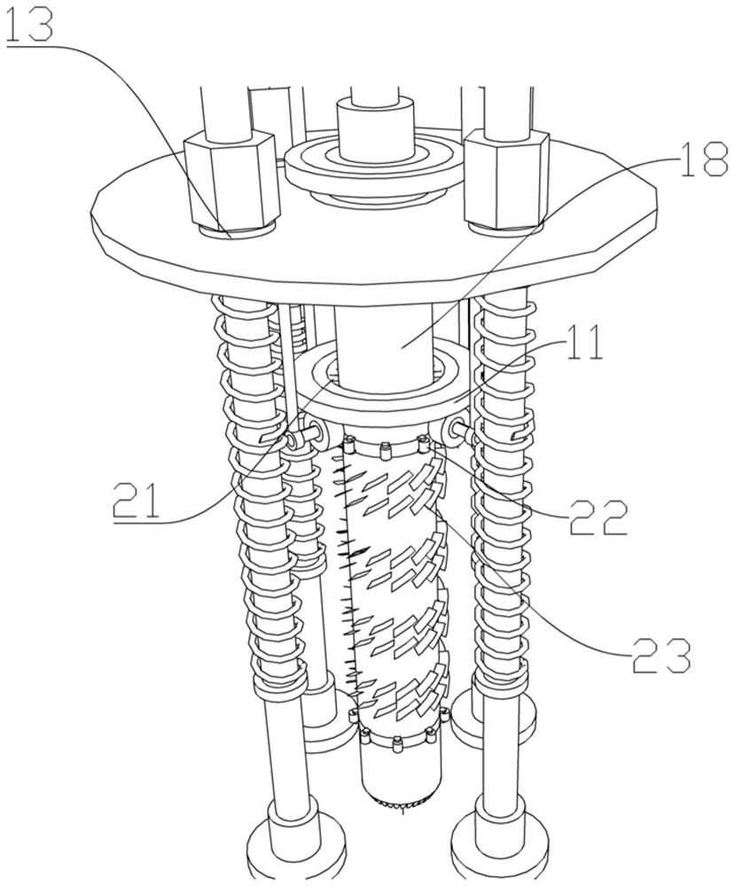
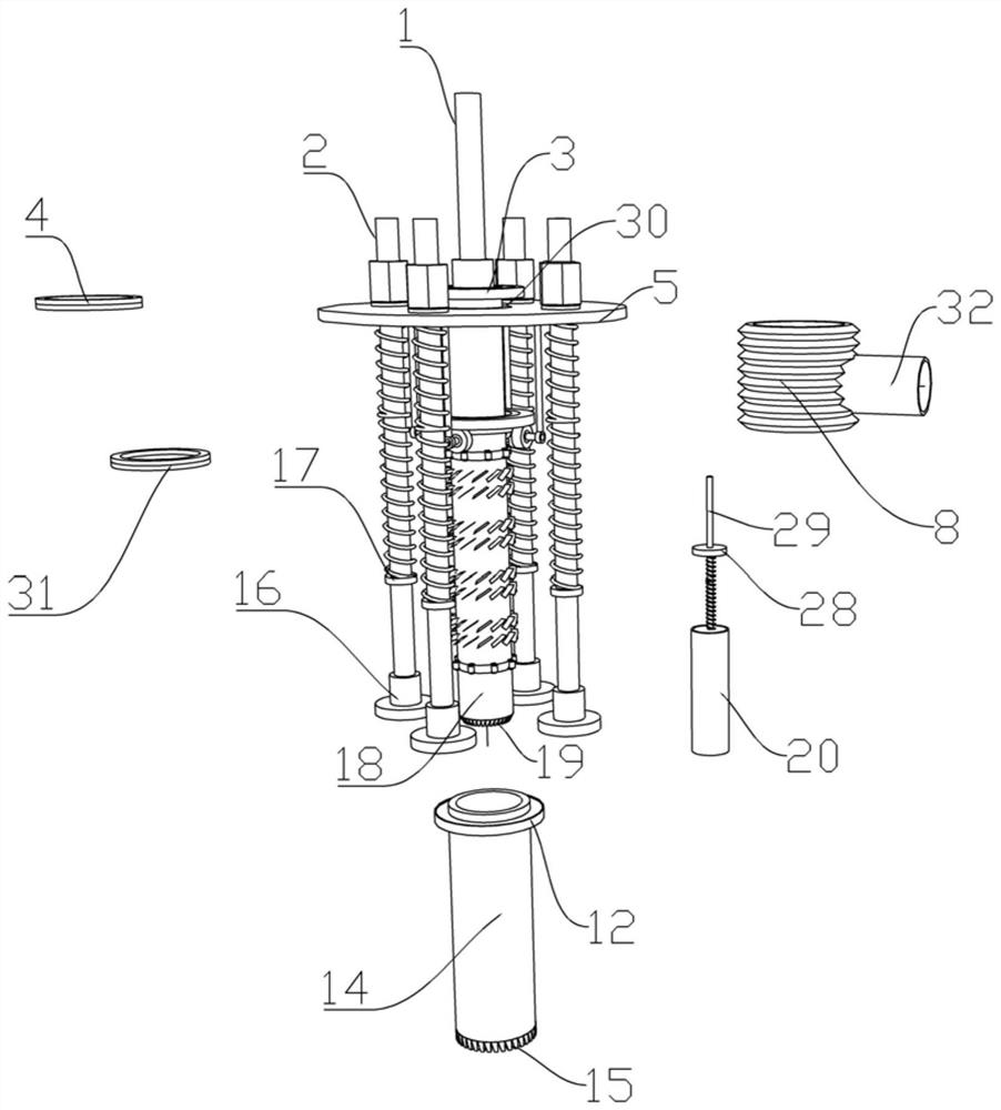
[0034] like Figure 1-6 As shown in the figure, a wall structure detection device for the renovation planning of an old residential area includes a fixed frame body, a first drill pipe 18, a second drill pipe 14, and a sampling pipe 20 components;

[0035] The middle part of the fixed frame body is rotatably connected with a first drill rod 18 through a first bearing 30 . The inside of the drill rod 18 is provided with a sampling tube 20 assembly that can extend in and out, and a second drill rod 14 is sleeved on the outside of the first drill rod 18 , and a space between the second drill rod 14 and the first drill rod 18 There is a ash layer, there are multiple groups of blast blades 23 in the ash layer, the first drill rod 18 is fixed with the upper toothed plate 11 through the first connecting rod 21, and the upper toothed plate 11 passes through the second bearing. 31 is rotatably connected to the lower toothed plate 12 at the upper end of the second drill pipe 14, and a ...


PUM


Abstract

The invention provides a wall structure detection device for old community reconstruction planning. The wall structure detection device comprises a fixed frame body, a first drill rod, a second drill rod and a sampling pipe assembly, a first drill rod is rotationally connected to the middle of the fixing frame body through a first bearing, a first drill rod head fixedly connected with an output shaft of the motor is arranged at one end of the first drill rod, a sampling pipe assembly capable of stretching in and out is arranged in the first drill rod, and the first drill rod is sleeved with a second drill rod; an ash passing layer is reserved between the second drill rod and the first drill rod, a plurality of sets of air blowing paddles are arranged in the ash passing layer, an upper fluted disc is fixed to the first drill rod through a first connecting rod, wall sampling can be conveniently completed by arranging the fixing frame body, the first drill rod, the second drill rod and the sampling pipe assembly, sampling is more accurate, and the sampling efficiency is improved. The service life of equipment can be remarkably prolonged, and dust in the sampling hole is prevented from falling from the sampling hole.

Description

technical field [0001] The present invention relates to a detection device, in particular to a wall structure detection device for the renovation planning of an old residential area. Background technique [0002] When planning and transforming the community, it is first necessary to test the wall structure. It is necessary to sample the wall and measure the thickness of each layer of the wall. The existing sampling equipment will form a gap between the drill pipe and the sampling hole when sampling, and During the drilling process of the drill pipe, the gas will be poured into the sampling hole and the dust will be taken out. The dust brought out will fall down along the wall, causing interference to the staff at the lower part of the wall, and also affecting the health of equipment operators. ; [0003] And the existing sampling equipment either does not have a cutting device, or is equipped with cutting teeth in the drill pipe, and the cutting teeth are ratchet-shaped. Wh...

Claims


Application Information

Patent Timeline
Patent Type & Authority Applications(China)
IPC IPC(8): G01B5/06G01N1/08G01N33/38
CPCG01B5/06G01N1/08G01N33/38
Inventor 喻常雄邱国潮袁启良陈平罗毅谢悦鑫祝鸿宇姚兰
Owner 湖南城市学院设计研究院有限公司
Why Eureka
Try Eureka