Assembly structure for photovoltaic support for roof erection

A technology of assembly structure and photovoltaic support, which is applied to the support structure of photovoltaic modules, photovoltaic modules, photovoltaic power generation, etc., can solve the problems of increasing the difficulty of operation for staff, loose photovoltaic panels, and difficult adjustments, and achieve the effect of large energy conversion effect

Inactive Publication Date: 2022-05-31
深圳市鑫旭源环保有限公司
View PDF0 Cites 1 Cited by
  • Summary
  • Abstract
  • Description
  • Claims
  • Application Information

AI Technical Summary

Problems solved by technology

[0003] At present, solar photovoltaic panels are widely used, not limited to the heating of daily water supply in households, more and more industrial production and power supply of public facilities need to use solar photovoltaic panels, and solar photovoltaic panels are difficult to directly connect with the installation interface It is not only inconvenient to install, but also extremely difficult to adjust in the future. Therefore, it is usually necessary to use photovoltaic brackets to install and fix photovoltaic panels. In use, due to the different heights in different seasons, the included angle between the sun's rays and the contact surface of the photovoltaic panel is different. It is well known that when the sun's rays are at right angles to the surface of the photovoltaic panel, the same can maximize the energy conversion efficiency. Therefore, according to different The elevation angle of the photovoltaic panel needs to be adjusted according to the sun height in different seasons, but most of the existing photovoltaic panel bracket installation and fixing devices need to adjust the angle of the photovoltaic panel by unscrewing all the bolts and unlocking the photovoltaic panel, so that after the bolts are removed Due to the lack of bolts, it is very easy to loosen and damage the photovoltaic panels
[0004] Moreover, when the assembly structure of the existing photovoltaic panel mounting bracket adjusts the elevation angle of the photovoltaic panel, it is not only necessary to unscrew all the bolts, but also to tighten the unscrewed bolts in turn after the angle adjustment is completed, so that It will increase the difficulty of the staff's operation and reduce their work efficiency, and the bolt holes need to be calibrated sequentially when re-screwing the bolts, thus further increasing the installation complexity
[0005] At the same time, most of the existing photovoltaic panel installation and fixing bracket devices are fixed in structure and need to be fixed on the installation plane by bolts. However, the later use of photovoltaic panels often needs to be replaced according to the actual strength of the photovoltaic panel conversion ability, so that it can To meet different light energy conversion efficiencies, and the existing photovoltaic panel mounting bracket device does not have the function suitable for different photovoltaic panel sizes due to its fixed structure, so it is necessary to develop a new type of photovoltaic panel installation bracket with a wide range of application and easy adjustment assembly structure

Method used


Image

  • Assembly structure for photovoltaic support for roof erection
  • Assembly structure for photovoltaic support for roof erection
  • Assembly structure for photovoltaic support for roof erection

Examples


Embodiment Construction

[0030] The technical solutions in the embodiments of the present invention will be clearly and completely described below with reference to the accompanying drawings in the embodiments of the present invention. Obviously, the described embodiments are only a part of the embodiments of the present invention, rather than all the embodiments. Based on the embodiments of the present invention, all other embodiments obtained by those of ordinary skill in the art without creative efforts shall fall within the protection scope of the present invention.

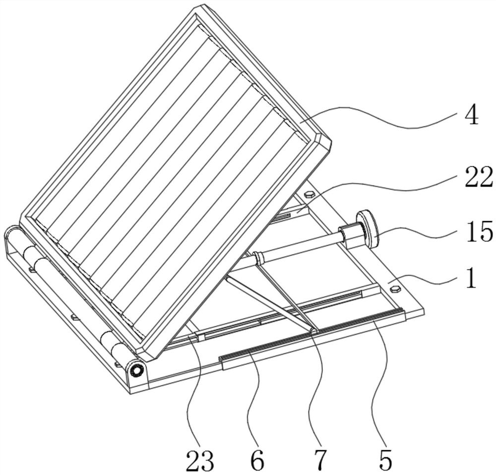
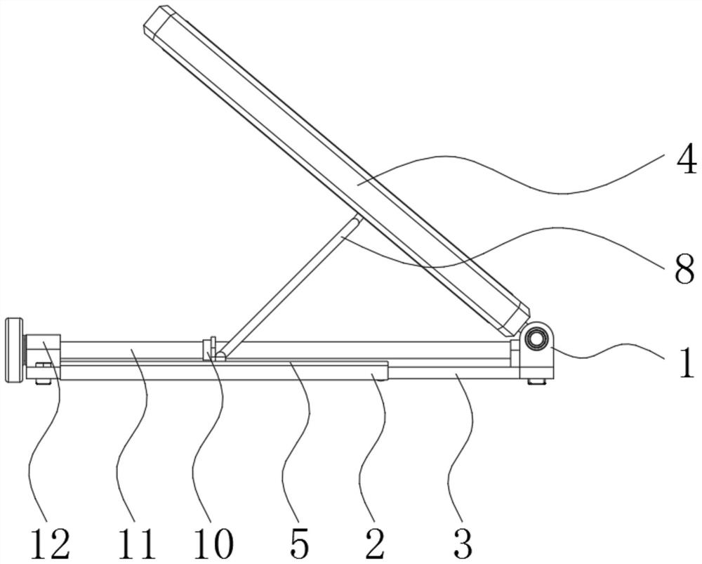
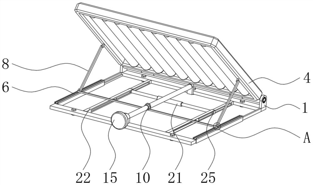
[0031] like Figure 1 to Figure 8 As shown, in the embodiment of the present invention, an assembly structure for a photovoltaic support for roof erection includes two fixing frames 1, and a connecting sleeve 2 and a connecting rod 3 are fixedly connected to the front and rear sides of the facing surfaces of the two fixing frames 1, respectively. A photovoltaic panel 4 is hinged on the left side of the top of the fixing frame 1, a slid...


PUM


Abstract

The invention belongs to the technical field of photovoltaic supports, and discloses an assembly structure for a photovoltaic support for roof erection, which comprises two fixing frames, the front and rear sides of the opposite surfaces of the two fixing frames are respectively and fixedly connected with a connecting sleeve and a connecting rod, and the left side of the top of each fixing frame is movably hinged with a photovoltaic panel. And a sliding frame is fixedly mounted at the top of the connecting sleeve, a sliding groove is formed in the top of the sliding frame, and a sliding block is movably clamped in the sliding groove. Through the sliding frame, the supporting rod and the rigid connecting plate, it can be guaranteed that the threaded rod can rotate through the fixing frame, meanwhile, accidental movement of the threaded rod can be limited, and then the threaded rod is rotated to drive the two sliding blocks to slide left and right along the inner wall of the sliding groove under cooperation of a threaded sleeve and the rigid connecting plate; through cooperation of the two supporting rods and the fixing frame, a worker can conveniently adjust the angle of the photovoltaic panel, so that the photovoltaic panel is suitable for the height of the sun in different seasons, and the energy conversion effect is achieved as much as possible.

Description

technical field [0001] The invention belongs to the technical field of photovoltaic supports, in particular to an assembly structure for a photovoltaic support for roof erection. Background technique [0002] The application advantages of solar support system in solar panel support are far more than simple production and installation; solar panels can also be flexibly moved according to the sun's rays and seasons; just like the initial installation, the slope of each solar panel can be tightened by moving it. Firmware, adjust the slope to suit different angles of light, and fix the solar panel exactly in the designated position by tightening it again. [0003] At present, the application of solar photovoltaic panels is extremely extensive, not only limited to the heating of household daily water supply, more and more industrial production and the power supply of public facilities require the use of solar photovoltaic panels, and solar photovoltaic panels are difficult to dir...

Claims


Application Information

Patent Timeline
Patent Type & Authority Applications(China)
IPC IPC(8): H02S20/23H02S20/30H02S30/10H02S30/00
CPCH02S20/23H02S20/30H02S30/10H02S30/00Y02E10/50
Inventor 林云唐保明
Owner 深圳市鑫旭源环保有限公司
Why Eureka
Try Eureka