Columnar electromagnetic wave lens

An electromagnetic wave, cylindrical technology, applied in the lens, electrical components, antennas and other directions, can solve the problems of high cost, insufficient density, two-dimensional randomness, etc., and achieve the effect of easy mass production, high product consistency, and stable electrical performance.

Active Publication Date: 2022-05-31
GUANGDONG FUSHUN TIANJI COMM CO LTD +1
View PDF11 Cites 0 Cited by
  • Summary
  • Abstract
  • Description
  • Claims
  • Application Information

AI Technical Summary

Problems solved by technology

[0005] The production of wrapped structures usually requires the use of molds. If there are too many layers, the process is too complicated and the cost is high, and the performance consistency of different individuals is usually poor
[0006]Caves are usually made by 3D printing, and the 3D printed structure is usually a single hot-melt material, which is currently suitable for 3D printing Hot-melt materials either have an improper dielectric constant or insufficient density, and when faced with making large-sized lenses, their weight is considerable, causing various difficulties in installation and use
[0007] Rolled structures are usually formed into cylinders or elliptical cylinders, such as the structure disclosed in Chinese Patent No.: 202010055740.0, titled "Manufacturing Method of Artificial Medium Multilayer Lenticular Lenses", the number of layers is easy to make more layer, and even if it does not conform to the theory of the classical model in the direction of the central axis of the cylinder or elliptical cylinder, the actual test data shows that its performance indicators can also meet the requirements of some specific scenarios
However, this kind of structure has its disadvantages: when the high dielectric constant granular material is a metal wire segment with a length of 2 to 3 mm, these metal wire segments are only scattered on the surface of the substrate, and these metal wire segments are quite large when the substrate is rolled up. So it is distributed along a spiral curved surface, which means that the lens of this structure has a plurality of metal wire segments on a certain part of it, and they almost have no length component in the radial direction of the rolled cylinder, that is, the lens of this structure although The metal line segment of the lens as a whole is three-dimensional random, but for any part of the lens, the metal line segment can only be two-dimensional random
This can easily lead to large deviations in performance indicators in all directions on the cylindrical lens

Method used


Image

  • Columnar electromagnetic wave lens
  • Columnar electromagnetic wave lens
  • Columnar electromagnetic wave lens

Examples


Embodiment 1

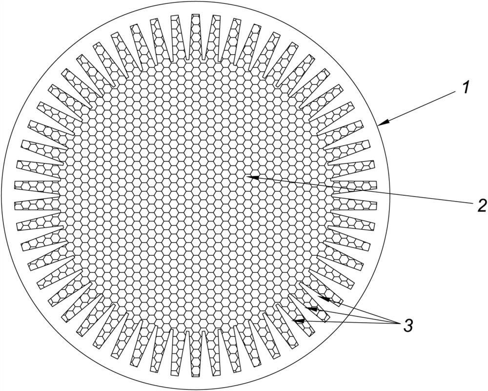
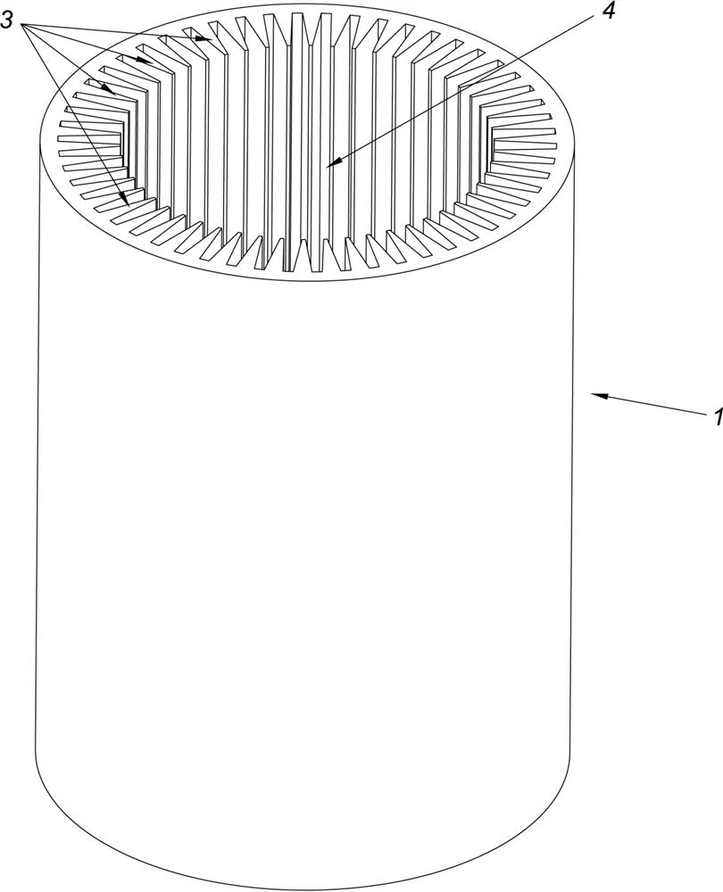
[0042] like figure 1 , figure 2 , image 3 , Figure 4 As shown, the cylindrical electromagnetic wave lens of this embodiment includes: an outer body 1 , a medium particle 2 , an upper end cap and a lower end cap (the upper end cap and the lower end cap are not shown in the figure). Among them: as figure 2 , image 3 , Figure 4 As shown, the outer body 1 is a cylindrical structure, and there are 54 tooth-like structures 3 evenly distributed in the circumferential direction inside the outer body 1. The outer body 1 and its tooth-like structures 3 are made of foamed materials through the mold. Made of foam. The tops of the tooth-like structures 3 are all facing the central axis C of the outer body 1; the space inside the outer body 1 is called the medium cavity 4, and the medium particles 2 are filled in the medium cavity 4, and there is no space between the medium particles 2. adhesive. The dielectric constant values ​​of the exobody 1 and the tooth-like structure 3 ...

Embodiment 2

[0046] like Figure 5 As shown, the difference between this embodiment and Embodiment 1 is that the medium particles are divided into first-type medium particles 21 and second-type medium particles 22 . The dielectric constant value of the first type of dielectric particles 21 is 1.8, the dielectric constant value of the second type of dielectric particles 22 is 2.1, and the layer formed by the first type of dielectric particles 21 is larger than that of the second type of dielectric particles 22 The layer is further away from the central axis of the exosome.

[0047] The physical structures of the first medium particles 21 and the second medium particles 22 are almost the same, and metal wire segments are embedded between the two layers of foamed materials, the difference lies in the number and / or length of the embedded metal wire segments. , so that they have different dielectric constant values.

Embodiment 3

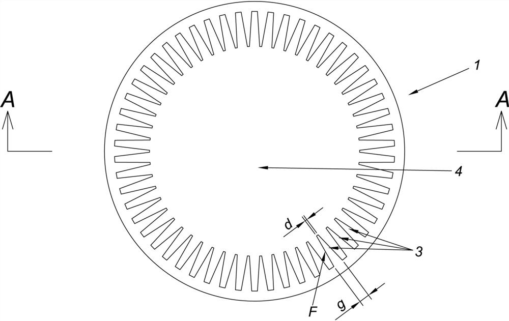
[0049] like Image 6 As shown, the difference between this embodiment and Embodiment 1 is that the number of tooth-like structures 3 of the outer body 1 is larger, and the roots of the tooth-like structures 3 are not connected.


PUM


Abstract

In order to obtain an electromagnetic wave lens product which is higher in production efficiency, lower in cost, light in weight, better in performance index and better in consistency of performance indexes in all directions on a cylindrical lens, the following technical scheme is adopted: the electromagnetic wave lens comprises medium particles and an outer structure; the outer structure body is of a cylindrical structure, and a plurality of tooth-shaped structures are distributed in the outer structure body in the circumferential direction. The width of the top of the tooth-shaped structure is smaller than that of the root of the tooth-shaped structure, and the top of the tooth-shaped structure faces the interior of the outer structure body. The space inside the outer structure is called as a medium cavity, and the medium cavity is filled with the medium particles; the dielectric constant value of the outer structure and the dielectric constant value of the tooth-shaped structure are lower than the dielectric constant value of the dielectric particles. The columnar electromagnetic wave lens has the advantages of being simple in structure, low in cost, easy to produce in batches, high in product consistency and stable in electrical performance.

Description

technical field [0001] The invention relates to the field of communication equipment production, and more particularly, to a cylindrical electromagnetic wave lens with a lower and lower dielectric constant from the inside to the outside. Background technique [0002] The Lumberg lens was proposed by RKLuneberg in 1944 based on the geometrical optics method. It is used as an antenna and a scatterer. It is mainly used in fast scanning systems, satellite communication systems, automotive anti-collision radars, radar reflectors and other fields. [0003] The classic model of Lumberg lens is: the permittivity of Lumberg lens from the spherical center to the outer diameter should change continuously from 2 to 1 following a certain mathematical law. However, such an ideal structure does not exist in nature, so the layered, dielectric constant step-change structure is often used in practical design to approximate the theoretical structure. [0004] In the prior art, the layered, di...

Claims


Application Information

Patent Timeline
IPC IPC(8): H01Q15/08G02B3/06
CPCH01Q15/08G02B3/06
Inventor 郑洪振芦永超李家铎凌武斌孙耀志陈旭林然王国栋尚春辉黄雅珊
Owner GUANGDONG FUSHUN TIANJI COMM CO LTD
Why Eureka
Try Eureka