A material width detection component and automatic control system of a wrapping machine tool
An automatic control system and component detection technology, which is applied to tires, household appliances, and other household appliances, can solve problems such as uniformity, automatic adjustment, and insufficient wrapping, so as to reduce detection time, reduce the output rate of waste circles, and The effect of improving the quality of finished products
- Summary
- Abstract
- Description
- Claims
- Application Information
AI Technical Summary
Problems solved by technology
Method used
Image
Examples
Embodiment 1
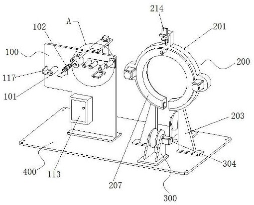
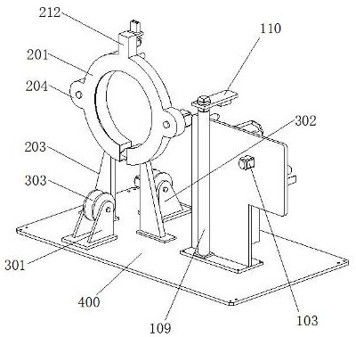
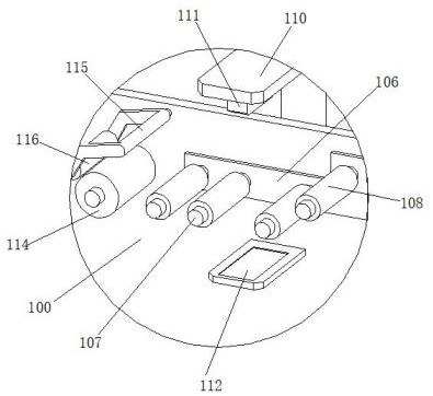
[0043] This embodiment 1 discloses a material width detection component of a cloth wrapping machine tool. figure 1 , attached figure 2 , attached image 3 and attached Figure 4 , the material width detection component includes a cloth discharge frame 100 , and a cloth discharge roller 101 is rotatably connected to the upper left end of the cloth discharge frame 100 . The cloth unloading frame 100 located at the upper right of the unloading roller 101 is provided with a cloth smoothing roller 102, and the rear side of the cloth discharging frame 100 is provided with a smoothing motor 103, and the smoothing motor 103 is connected with the cloth smoothing roller 102, A spiral pattern 105 is symmetrically arranged on the circumferential surface of the cloth smoothing roller 102 in front and rear mirror images.
[0044] A strip plate 106 is fixed on the cloth unloading frame 100 located on the right side of the cloth smoothing roller 102, and a row of cloth guide rollers 107 i...
Embodiment 2
[0048] This embodiment 2 discloses an automatic control system for a cloth wrapping machine tool. figure 1 and attached figure 2 , including the material width detection component, the traveler winding mechanism 200, the traveler rotation driving mechanism 300 and the bottom plate 400, wherein the material width detection component, the traveler winding mechanism 200 and the traveler rotation driving mechanism 300 are all fixedly arranged on the upper surface of the bottom plate 400 .
[0049] Reference attached Figure 4 -Attached Figure 9 , the wire loop winding mechanism 200 includes a non-closed-loop annular transmission case 201, and a fracture 202 is provided at the lowermost end of the annular transmission case 201. The width of the fracture 202 at the lower end of the annular transmission case 201 is set to 3-8 cm. The diameter of the ring is set to facilitate the insertion of the traveler. Supporting legs 203 are connected to the annular transmission case 201 lo...
Embodiment 3
[0056] On the basis of Embodiment 1 and Embodiment 2, the present invention further provides another embodiment. The width measuring sensor of the present invention adopts a linear CCD image sensor. Based on the images obtained by the CCD image sensor, statistical The number of pixels in the image area, combined with the corresponding width of each pixel, to calculate the width measurement value;
[0057] Further, the applicant found in practice that image degradation phenomena such as blur, distortion, noise interference, etc. often occur in the process of CCD image acquisition, thereby affecting the width measurement results. In view of this, the applicant further proposes a compensation algorithm for CCD images. , the specific steps include:
[0058] Step 1): Perform image filtering preprocessing on the original image collected by the CCD;
[0059] Step 2): Correct the preprocessed image in step 1), including filling the blank area of the pixel space with morphological o...
PUM
| Property | Measurement | Unit |
|---|---|---|
| width | aaaaa | aaaaa |
Abstract
Description
Claims
Application Information
 - Generate Ideas
- Intellectual Property
- Life Sciences
- Materials
- Tech Scout
- Unparalleled Data Quality
- Higher Quality Content
- 60% Fewer Hallucinations
Browse by: Latest US Patents, China's latest patents, Technical Efficacy Thesaurus, Application Domain, Technology Topic, Popular Technical Reports.
© 2025 PatSnap. All rights reserved.Legal|Privacy policy|Modern Slavery Act Transparency Statement|Sitemap|About US| Contact US: help@patsnap.com


