Tool box for automobile detection equipment
A technology for testing equipment and toolboxes, which is applied to manufacturing tools, tool storage devices, etc., can solve the problems of reducing the service life of toolboxes, collisions, no wrench and screwdriver clamping, etc., to improve the clamping firmness and improve the placement space. , the effect of avoiding collision
- Summary
- Abstract
- Description
- Claims
- Application Information
AI Technical Summary
Problems solved by technology
Method used
Image
Examples
Embodiment 1
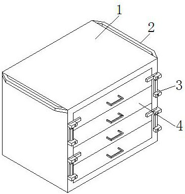
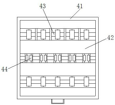
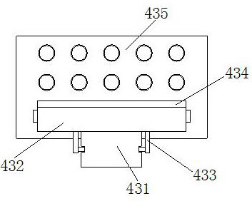
[0022] as attached figure 1 to attach Figure 5 Shown:
[0023] The present invention is a toolbox for automobile testing equipment, its structure includes a box body 1, a handle 2, a lever 3, and a placement mechanism 4, the handle 2 is welded on the outside of the upper end of the box body 1, and the lever 3 is installed on the The front end of the body 1, the clamp rod 3 is in conflict with the front end of the placement mechanism 4, the placement mechanism 4 is slidably installed inside the box body 1, and the placement mechanism 4 includes a drawer 41, a sponge pad 42, a wrench placement mechanism 43, a screwdriver Engagement mechanism 44, said drawer 41 inner side bottom is embedded with sponge pad 42, and wrench placement mechanism 43 is installed inside drawer 41, said screwdriver engagement mechanism 44 is arranged inside drawer 41, and said sponge pad 42 is positioned at wrench The placement mechanism 43 is outside, and the sponge pad 42 is located outside the scre...
Embodiment 2
[0030] as attached Image 6 to attach Figure 7 Shown:
[0031] Wherein, the screwdriver engagement mechanism 44 includes a guide rod 441, a sliding block 442, a locking ball 443, and a fastening mechanism 444. The guide rod 441 is fixedly installed inside the drawer 41, and the sliding block 442 is slidably installed on the upper end of the guide rod 441. , the outer side of the sliding block 442 is provided with a locking ball 443, and the locking ball 443 is engaged with the inside of the sponge pad 42, the locking mechanism 444 is installed on the upper end of the sliding block 442, and there are two locking balls 443, They are respectively arranged at the left and right ends of the sliding block 442 , and are engaged with the inside of the sponge pad 42 by the locking ball 443 , so as to fix and adjust the sliding distance of the sliding block 442 on the guide rod 441 .
[0032] Wherein, the fastening mechanism 444 includes a fastening plate 44a, a spring 44b, a corruga...
PUM
 Abstract
Description
Claims
Application Information
 - R&D
- Intellectual Property
- Life Sciences
- Materials
- Tech Scout
- Unparalleled Data Quality
- Higher Quality Content
- 60% Fewer Hallucinations
Browse by: Latest US Patents, China's latest patents, Technical Efficacy Thesaurus, Application Domain, Technology Topic, Popular Technical Reports.
© 2025 PatSnap. All rights reserved.Legal|Privacy policy|Modern Slavery Act Transparency Statement|Sitemap|About US| Contact US: help@patsnap.com


