Explosion-proof flame-retardant electrical control cabinet capable of efficiently bundling

An electrical control cabinet, flame-retardant technology, applied to electrical components, substation/switch layout details, substation/power distribution device shell, etc., can solve the problems of complex clustering, long clustering process, confusion, etc., and achieve high clustering efficiency, The effect of reducing the winding rate and increasing the stability

Pending Publication Date: 2022-05-27
UNIV FOR SCI & TECH ZHENGZHOU
View PDF1 Cites 0 Cited by
  • Summary
  • Abstract
  • Description
  • Claims
  • Application Information

AI Technical Summary

Problems solved by technology

[0004] (1) In response to this, Chinese Patent No. CN213989825U proposes a high-efficiency heat-dissipating electrical control cabinet with a clean structure, which can improve the heat dissipation capacity of the radiator to the inside of the electrical control cabinet by installing multiple heat sinks and cooling fans, preventing Under the long-term use of the electrical control cabinet, the temperature of the electronic equipment inside the electrical control cabinet will rise, resulting in damage to the electronic equipment due to excessive temperature, making the electrical control cabinet unable to use normally. In the above patents, the electrical control cabinet is not The internal structure is processed, so that many wire harnesses inside the electrical control cabinet are easy to be placed scatteredly, causing problems such as winding, and the local bundled lines are easy to fall off, which is more complicated when bundled, making the bundled process longer and easy to cause confusion. ;
[0005] (2) The bundling inside the electrical control cabinet in the prior art is easily affected by the location, which makes the bundling inside the electrical control cabinet easy to be messy, making later maintenance more complicated

Method used


Image

  • Explosion-proof flame-retardant electrical control cabinet capable of efficiently bundling
  • Explosion-proof flame-retardant electrical control cabinet capable of efficiently bundling
  • Explosion-proof flame-retardant electrical control cabinet capable of efficiently bundling

Examples


Embodiment 1

[0033] like Figure 2-Figure 4As shown, the clustering mechanism includes a clustering ring 8, the two ends of the inner wall of the clustering ring 8 are fixedly provided with a limit block 10, the middle position of one end of the outer wall of the clustering ring 8 is fixedly provided with a first positioning rod 11, and one end of the outer wall of the first positioning rod 11 A connecting rod 12 is interspersed, and the other end of the first positioning rod 11 outer wall is interspersed with a first spring 13, and one end of the first positioning rod 11 is fixedly provided with a first spacer 14, and the two ends on one side of the connecting rod 12 are arranged Fixing strips 15 are fixedly arranged, and one end of the outer wall of the two fixing strips 15 is interspersed with the two ends on one side of the outer wall of the cluster ring 8 respectively, and the other end of the outer wall of the two fixing strips 15 is connected with the two ends of the other side of th...

Embodiment 2

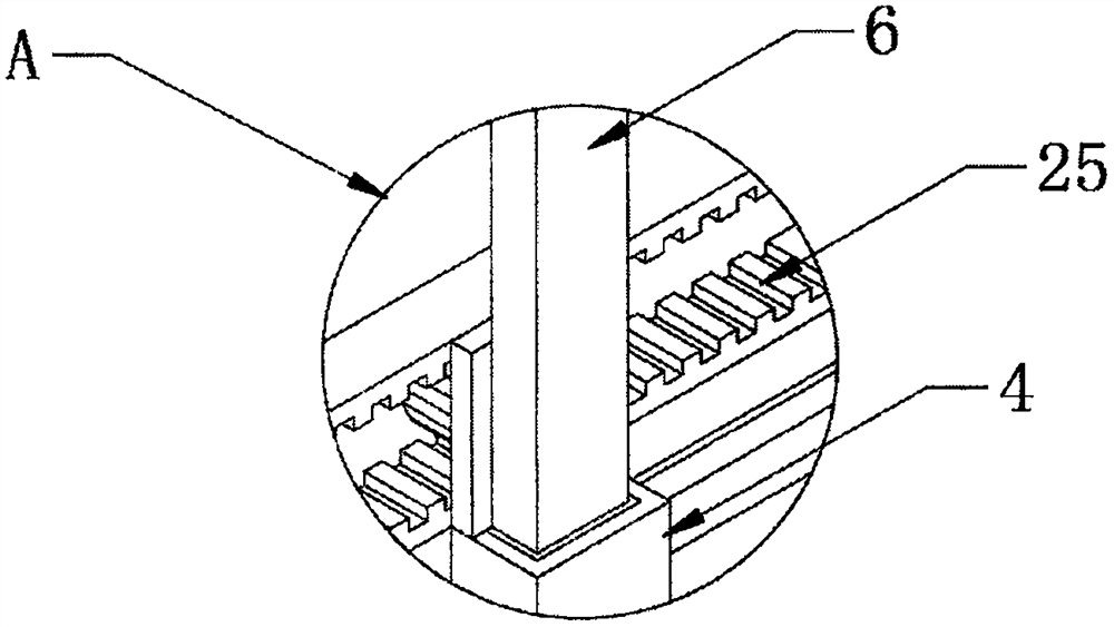
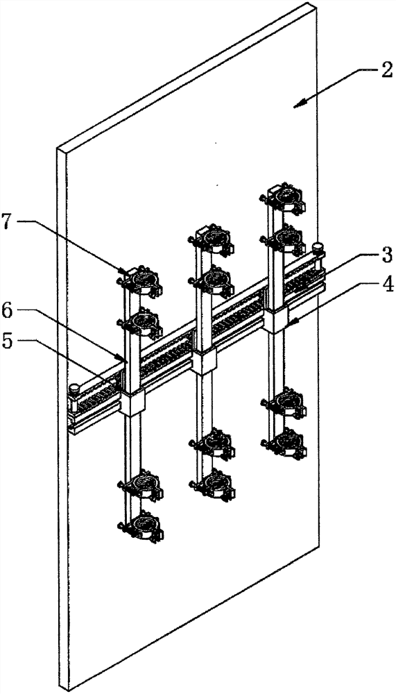
[0035] like Figure 4-Figure 6 As shown, one end of the top of the three positioning blocks 4 is fixedly provided with a baffle plate 23, and the middle positions on one side of the three baffle plates 23 are all rotated to be provided with a gear 24, and the top of the slide rail 3 is fixedly provided with a first rack 25, One end of the tooth surfaces of the three gears 24 is meshed with the tooth surface of the first rack 25, and the two ends of the top of the first rack 25 are fixedly equipped with a third positioning rod 26, and one end of the outer walls of the two third positioning rods 26 are connected to each other. The second tooth bar 27 is interspersed, and one end of the outer wall of the two third positioning rods 26 is inserted and connected with the two ends of the top of the second tooth bar 27 respectively, and the other end of the outer wall of the two third positioning rods 26 is interspersed with the second tooth bar. Three springs 28, the tops of the two ...

Embodiment 3

[0037] like Figure 8 As shown, one end on one side of the electrical control cabinet body 1 is hingedly provided with a protective door 31, and the four sides on one side of the electrical control cabinet body 1 are fixedly provided with sealing strips 30, and the four sides on one side of the protective door 31 are all fixed. A sealing groove 32 is provided, so that the electrical control cabinet body 1 can obtain the effect of explosion-proof and flame retardant, and reduce the immersion of water vapor and water flow, etc., so as to protect the electrical control cabinet body 1 .

[0038] The working principle of this embodiment: when it is necessary to use an explosion-proof and flame-retardant electrical control cabinet that can be clustered efficiently, such as Figure 1-Figure 3 and Figure 4-Figure 7 As shown, when it is necessary to bundle multiple electric wires inside the electrical control cabinet body 1, the worker pulls up the second rack 27, so that the second ...


PUM


Abstract

The invention discloses an explosion-proof flame-retardant electrical control cabinet capable of efficiently bundling, which comprises an electrical control cabinet body, a protection plate and a slide rail, the protection plate is fixedly arranged at one end of the inner wall of the electrical control cabinet body, the slide rail is fixedly arranged in the middle of one side of the protection plate, and three positioning blocks are slidably arranged on one side of the slide rail at equal intervals. A bundling mechanism is fixedly arranged on one side of each fixing block, and a positioning mechanism is fixedly arranged in the middle of each fixing block; according to the explosion-proof flame-retardant electrical control cabinet capable of efficiently bundling, a plurality of lines on the inner wall of the electrical control cabinet body are extruded into a bundling ring, and through positioning of second positioning rods fixed to the two ends of one side of a positioning rod, second springs penetrating through the outer walls of the second positioning rods are extruded, so that the lines in the bundling ring are more compact, and the reliability of the bundling ring is improved. The stability of line bundling is improved, the bundling efficiency of the electrical control cabinet body is higher, and the practicability of the electrical control cabinet body is improved.

Description

technical field [0001] The invention relates to the technical field of an explosion-proof and flame-retardant electrical control cabinet that can be bundled efficiently, in particular to an explosion-proof and flame-retardant electrical control cabinet that can be bundled efficiently. Background technique [0002] The control cabinet is to assemble the switchgear, measuring instrument, protective device and auxiliary equipment in the closed or semiclosed metal cabinet or on the screen width according to the requirements of electrical wiring. and the safety of surrounding equipment. During normal operation, the circuit can be connected or disconnected by means of a manual or automatic switch. Cut off the circuit or alarm with the help of protective electrical appliances in case of failure or abnormal operation. Various parameters in operation can be displayed by means of measuring instruments, and some electrical parameters can also be adjusted to prompt or send out signals...

Claims


Application Information

Patent Timeline
Patent Type & Authority Applications(China)
IPC IPC(8): H02B1/20H02B1/30H02B1/34
CPCH02B1/202H02B1/30H02B1/34
Inventor 左明鑫张亚超王敬伟
Owner UNIV FOR SCI & TECH ZHENGZHOU
Why Eureka
Try Eureka