
Steel bar binding machine

A binding machine and steel bar technology, which is applied in construction, building structure, and building material processing, etc., can solve the problems of difficult large-scale promotion, heavy structure, and low binding efficiency, so as to overcome wrist pain and adaptability to working conditions , Improve the effect of bundling efficiency

Pending Publication Date: 2020-05-12
POSITEC POWER TOOLS (SUZHOU) CO LTD
View PDF0 Cites 4 Cited by
  • Summary
  • Abstract
  • Description
  • Claims
  • Application Information

AI Technical Summary

Problems solved by technology

However, when the steel bars are bound manually, the following problems will inevitably exist: inconvenient operation, low binding efficiency, long binding time, easy to hurt hands
[0004] Although the existing fully automatic steel bar binding machine has a high degree of automation, it also introduces some new problems
First of all, on the one hand, since the fully automatic steel bar binding machine has a fixed-sized engaging part at the outlet end that engages with the steel bar, for steel bars with very dense spacing, such as columns, beams, etc., because the engaging part cannot be snapped in, it cannot be clamped. Bind the steel bars at the above positions; on the other hand, because the wire reels in the current automatic steel bar binding machine are consumables, and are special steel wire reels, their wire diameters, material properties, etc. have special requirements, resulting in relatively high cost of use. Therefore, on the whole, the fully automatic steel bar binding machine has poor adaptability to working conditions, high cost, and is difficult to promote on a large scale
In addition, the automatic steel bar binding machine also has problems such as relatively heavy structure and inconvenient use; the price of the machine is high

Method used

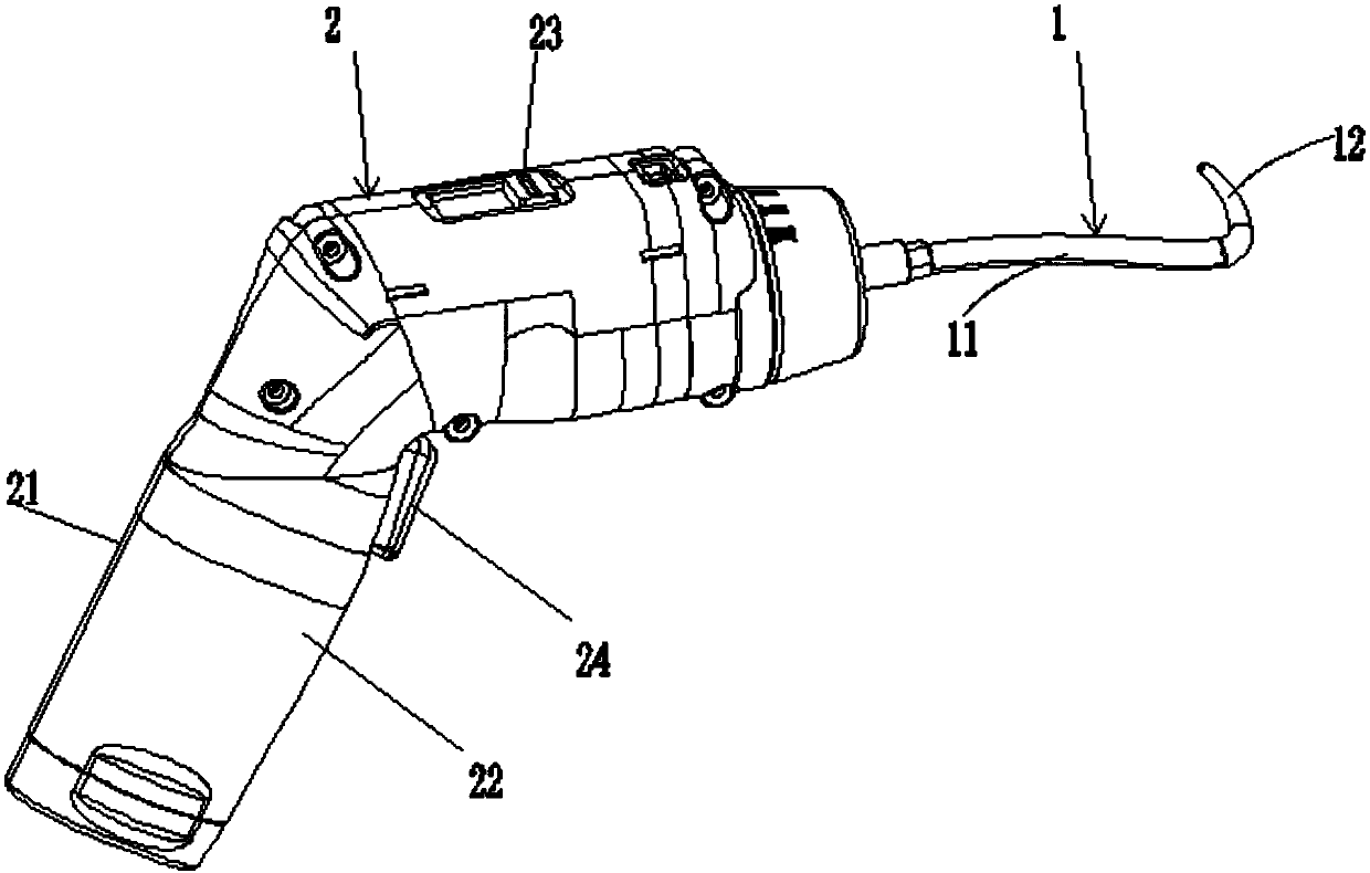
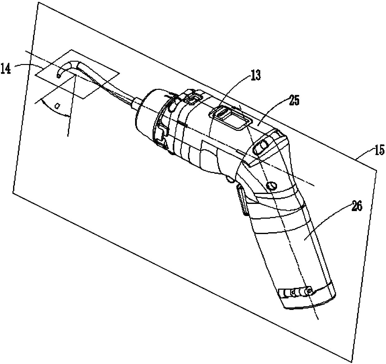
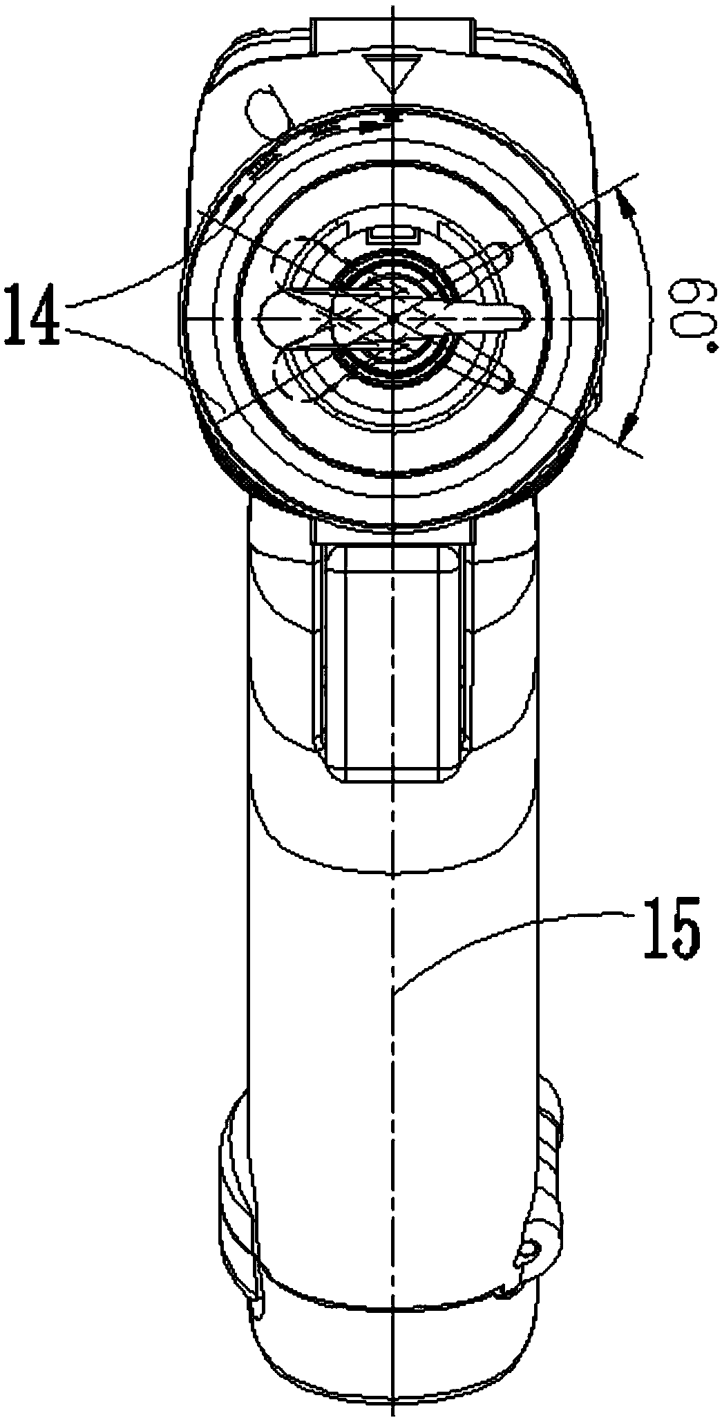

Image

  • Steel bar binding machine
  • Steel bar binding machine
  • Steel bar binding machine

Examples


Embodiment Construction

[0049] The technical solution of the present invention will be described in detail below in conjunction with the accompanying drawings and specific embodiments. It should be understood that these embodiments are only used to illustrate the present invention and are not intended to limit the scope of the present invention. After reading the present invention, those skilled in the art Modifications to various equivalent forms of the present invention fall within the scope defined by the appended claims of the present application.

[0050] It should be noted that when an element is referred to as being “disposed on” another element, it may be directly on the other element or there may also be an intervening element. When an element is referred to as being "connected to" another element, it can be directly connected to the other element or intervening elements may also be present. As used herein, the terms "vertical", "horizontal", "upper", "lower", "left", "right" and similar exp...


PUM


Abstract

The invention discloses a steel bar binding machine. The steel bar binding machine comprises a shell, a working head, a power mechanism, a signal acquisition unit and a control unit, wherein the working head is used for twisting joint of steel wires, and the working head comprises a body part extending out of the shell in a first extending direction and a working part arranged at the end, far awayfrom the shell, of the body part; the working part has a second extending direction different from the first extending direction, and the body part defines a first axis in the first extending direction; the power mechanism is used for driving the working head to rotate around the first axis; the signal acquisition unit is used for acquiring a signal representing the twisting joint state of the steel wires; and the control unit is electrically connected with the power mechanism and the signal acquisition unit, and the control unit is used for controlling the working head to stop rotating underthe condition that the signal acquisition unit acquires a signal indicating that the steel wires finish twisting joint. With the steel bar binding machine, the operation convenience can be improved and the working condition adaptability is higher.

Description

technical field [0001] The invention relates to the technical field of construction site tools and equipment, in particular to a steel bar binding machine. Background technique [0002] In the construction of reinforced concrete buildings, it is usually necessary to bundle the intersections of steel bars and other positions to position and fix the steel bar skeleton. At present, comparatively general on the construction site, still adopt manual mode to carry out bundling to steel bar. When the reinforcement is bundled manually, the ordinary galvanized steel wire is usually bound to the position where the reinforcement needs to be fixed by using a manual binding tool. However, when the steel bars are bound manually, the following problems inevitably exist: inconvenient operation, low binding efficiency, time-consuming binding, and easy hand injury. Especially when the operator repeats the action of steel wire reaming, the phenomenon of soreness is particularly prone to occu...

Claims


Application Information

Patent Timeline
Patent Type & Authority Applications(China)
IPC IPC(8): E04G21/12
CPCE04G21/123
Inventor 钱富张士松钟红风汪飞张振
Owner POSITEC POWER TOOLS (SUZHOU) CO LTD
Learn More