A storage and transportation launch box precision adjustment device and adjustment method thereof
A technology of an adjustment device and an adjustment method, which is applied in the field of storage and transportation boxes, can solve the problems of out-of-tolerance positioning error, reduce storage and transportation efficiency, and be difficult to guarantee, and achieve the effect of ensuring installation and positioning accuracy.
- Summary
- Abstract
- Description
- Claims
- Application Information
AI Technical Summary
Problems solved by technology
Method used
Image
Examples
Embodiment 1
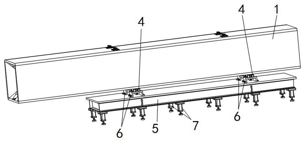
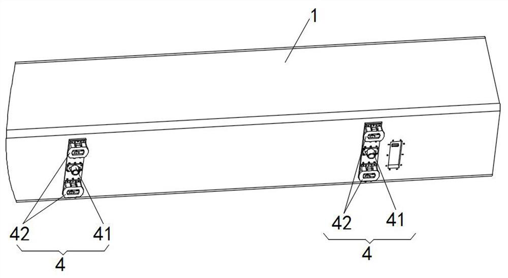
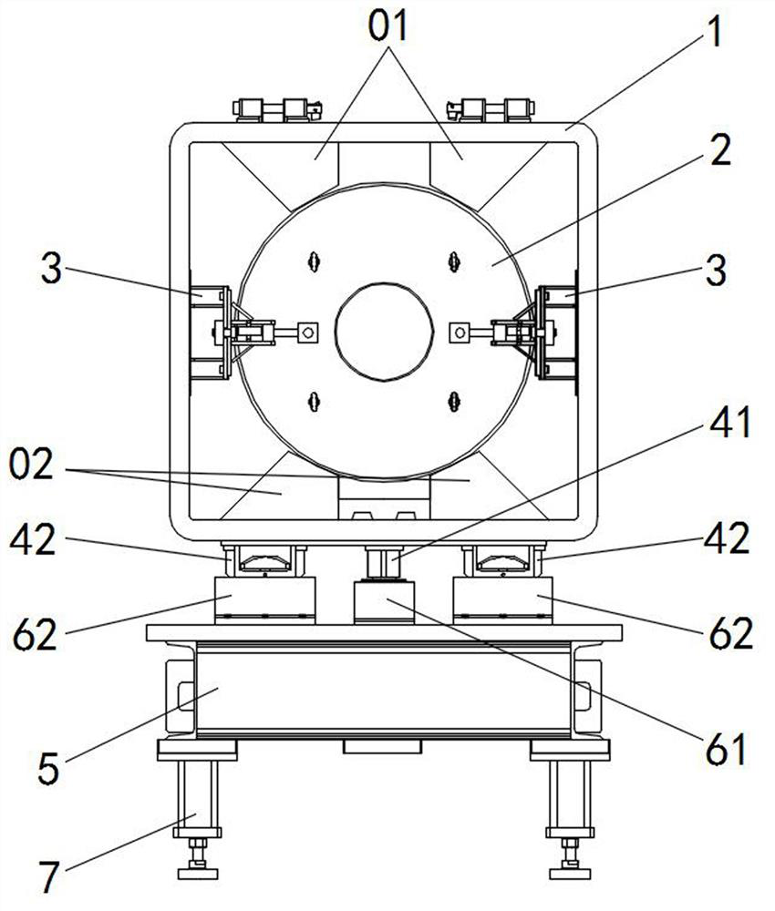
[0044] A storage and transportation launch box precision adjustment device and adjustment method thereof in this embodiment, such as figure 1 and figure 2 As shown, it includes a storage and transportation box body 1 and a simulation debugging platform 5 arranged at the bottom of the storage and transportation box body 1. The interior of the storage and transportation box body 1 is provided with a sample column 2 slidably along the axial direction. The storage and transportation box body 1 The end faces of the corresponding sample column 2 on the inner walls of one end are provided with a loose spring locking device 3; The two ends are respectively provided with a locking and positioning assembly 6 connected with the locking adjustment assembly 4 , and a plurality of lifting and supporting devices 7 are linearly arranged on both sides of the bottom of the simulation debugging platform 5 .
[0045] The shape of the sample column 2 is the same as that of the solid part, and is...
Embodiment 2
[0051] This embodiment is further optimized on the basis of Embodiment 1, such as image 3 and Figure 4 As shown, the upper and lower sides of the interior of the storage box body 1 are provided with an upper guide rail 01 and a lower guide rail 02 in parallel, the bottom of the upper guide rail 01 is provided with an upper sliding arc groove, and the top of the lower guide rail 02 is provided with an upper sliding arc groove. A lower sliding arc groove is provided, and the upper sliding arc groove and the lower sliding arc groove are fitted into an envelope circle; the top of the sample column 2 is slidably connected to the upper sliding arc groove at the bottom of the upper guide rail 01 , the bottom of the sample column 2 is slidably connected with the lower sliding arc groove on the top of the lower guide rail 02, and the outer contour of the sample column 2 is set corresponding to the enveloping circle.
[0052] During the sliding process of the sample column 2, the sli...
Embodiment 3
[0056] This embodiment is further optimized on the basis of the above-mentioned Embodiment 1 or 2, such as Figure 5 shown, Figure 5 A in the figure represents a partial enlarged view of the place A. The loose snap lock device 3 includes a positioning frame 31, a movable frame 32, an elastic limit block 33, and a limit belt 34. The positioning frame 31 is fixedly installed on the storage box body. On the inner walls of both sides of one end of 1, a movable frame 32 is provided on the positioning frame 31 along the axial direction of the storage and transportation box body 1, and an elastic limit block 33 is provided on the side of the movable frame 32 close to the sample column 2. , a limit band 34 is arranged on the free end of the movable frame 32 , and the free end of the limit band 34 is connected with the end face of the sample column 2 .
[0057] The positioning frame 31 is directly fixed and installed on the inner walls on both sides of one end of the storage box body...
PUM
 Abstract
Description
Claims
Application Information
 - R&D
- Intellectual Property
- Life Sciences
- Materials
- Tech Scout
- Unparalleled Data Quality
- Higher Quality Content
- 60% Fewer Hallucinations
Browse by: Latest US Patents, China's latest patents, Technical Efficacy Thesaurus, Application Domain, Technology Topic, Popular Technical Reports.
© 2025 PatSnap. All rights reserved.Legal|Privacy policy|Modern Slavery Act Transparency Statement|Sitemap|About US| Contact US: help@patsnap.com


