Painting device for building decoration, control system based on Internet of Things and construction method

A technology of architectural decoration and painting, which is applied in the direction of building construction, construction, spraying devices, etc., can solve the problems of poor automation effect, poor painting effect, and low efficiency of painting devices, and achieve the effect of improving stability

Pending Publication Date: 2022-05-27
深圳市建和建设集团有限公司
View PDF1 Cites 0 Cited by
  • Summary
  • Abstract
  • Description
  • Claims
  • Application Information

AI Technical Summary

Problems solved by technology

[0004] The existing painting device has poor automation effect, and the painting effect is often poor due to paint agglomeration during use, and the efficiency of the existing painting device is low

Method used


Image

  • Painting device for building decoration, control system based on Internet of Things and construction method
  • Painting device for building decoration, control system based on Internet of Things and construction method
  • Painting device for building decoration, control system based on Internet of Things and construction method

Examples


Embodiment 1

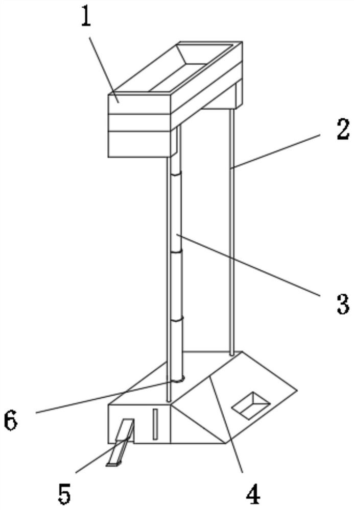
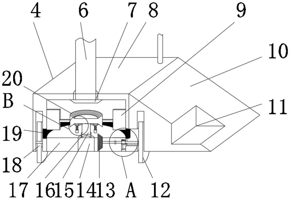
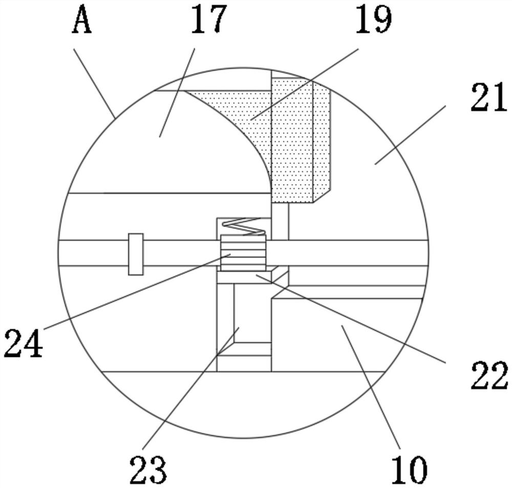
[0034] like Figure 1-2 As shown, a painting device for architectural decoration includes a driving mechanism 4, the driving mechanism 4 is drivingly connected with a driving shaft 6, the driving shaft 6 is drivingly connected with a lifting rod 3, and the end of the lifting rod 3 away from the driving shaft 6 is rotatably connected with a painting mechanism 1. The bottom of the painting mechanism 1 is communicated with the driving mechanism 4 by being provided with an infusion tube 2. The driving mechanism 4 includes a driving mechanism housing 8, a driving pressure plate 10 and a bottom plate 17. The upper end surface of the bottom plate 17 is provided with a sealing bellows 19. The driving mechanism shell The body 8 is elastically sleeved on the upper end face of the bottom plate 17 through the sealing bellows 19, the driving pressing plate 10 is fixedly connected to the side end face of the driving mechanism housing 8, and the driving pressing plate 10 is rotatably connecte...

Embodiment 2

[0037] On the basis of Example 1, as Figure 1-3 As shown, a cavity is formed between the drive mechanism housing 8 and the bottom plate 17, the middle of the bottom plate 17 is embedded with a driving motor 14, the driving motor 14 is drivingly connected with a motor rotor 16, and a rotating rod 15 is slidably sleeved inside the motor rotor 16. , the end of the rotating rod 15 away from the motor rotor 16 is fixedly connected with a stirring paddle 9, and the stirring paddle 9 rotates coaxially with the motor rotor 16, and the stirring paddle 9 is rotatably connected in the cavity.

[0038] When in use, the cavity is filled with stucco paint, and the rotation of the motor rotor 16 is controlled by the driving motor 14. The rotating rod 15 can rotate coaxially with the motor rotor 16 through the pins and keys while maintaining vertical sliding, and the rotation of the driving motor 14 Drive the rotation of the stirring paddle 9, so as to stir the paint in the cavity to avoid t...


PUM


Abstract

The invention discloses a painting device for building decoration, a control system based on the Internet of Things and a construction method.The painting device for building decoration comprises a driving mechanism, the driving mechanism is in driving connection with a driving shaft, the driving shaft is in driving connection with a lifting rod, and the end, away from the driving shaft, of the lifting rod is rotationally connected with a painting mechanism; the bottom of the painting mechanism communicates with the driving mechanism through a liquid conveying pipe, the driving mechanism comprises a driving mechanism shell, a driving pressing plate and a bottom plate, a sealing corrugated pipe is arranged on the upper end face of the bottom plate, and the driving mechanism shell is elastically connected to the upper end face of the bottom plate in a sleeving mode through the sealing corrugated pipe; and the driving pressing plate is fixedly connected to one side of the side end face of the driving mechanism shell, a driving wheel is rotatably connected to the interior of the driving pressing plate, a driven wheel is rotatably connected to the interior of the driving mechanism shell, and the device effectively improves the convenience and automation degree of painting.

Description

technical field [0001] The invention relates to the technical field of spraying equipment, in particular to a painting device for building decoration, a control system and a construction method based on the Internet of Things. Background technique [0002] Stucco refers to the cleaning or smearing utensils made of bundles of hair brown, etc.: brushes, brushes, board brushes, especially tools for makeup and powder or the protective layer applied to the surface of the building. [0003] Chinese Invention Patent Publication No. CN109235848B, the present invention relates to the technical field of industrial wall painting, more specifically to an industrial wall painting device, comprising a fixed base, a lifting device, a left and right sliding member, a grinding member, a painting member and a painting device, First move the left and right sliding members to the lowest end, then turn the handle clockwise, the handle drives the lead screw III to rotate, and the clockwise lead s...

Claims


Application Information

Patent Timeline
Patent Type & Authority Applications(China)
IPC IPC(8): E04F21/08B05B15/25
CPCE04F21/08B05B15/25
Inventor 吕二康刘姿人梁雁
Owner 深圳市建和建设集团有限公司
Why Eureka
Try Eureka