A uniform painting equipment for I-beam
A kind of I-beam, uniform technology, applied in the direction of pretreatment surface, device for coating liquid on the surface, coating, etc., can solve the problems of cumbersome operation process, low work efficiency, labor consumption, etc., to achieve simple operation and improve work efficiency. Efficiency and manpower saving effect
- Summary
- Abstract
- Description
- Claims
- Application Information
AI Technical Summary
Problems solved by technology
Method used
Image

Examples
Embodiment 1
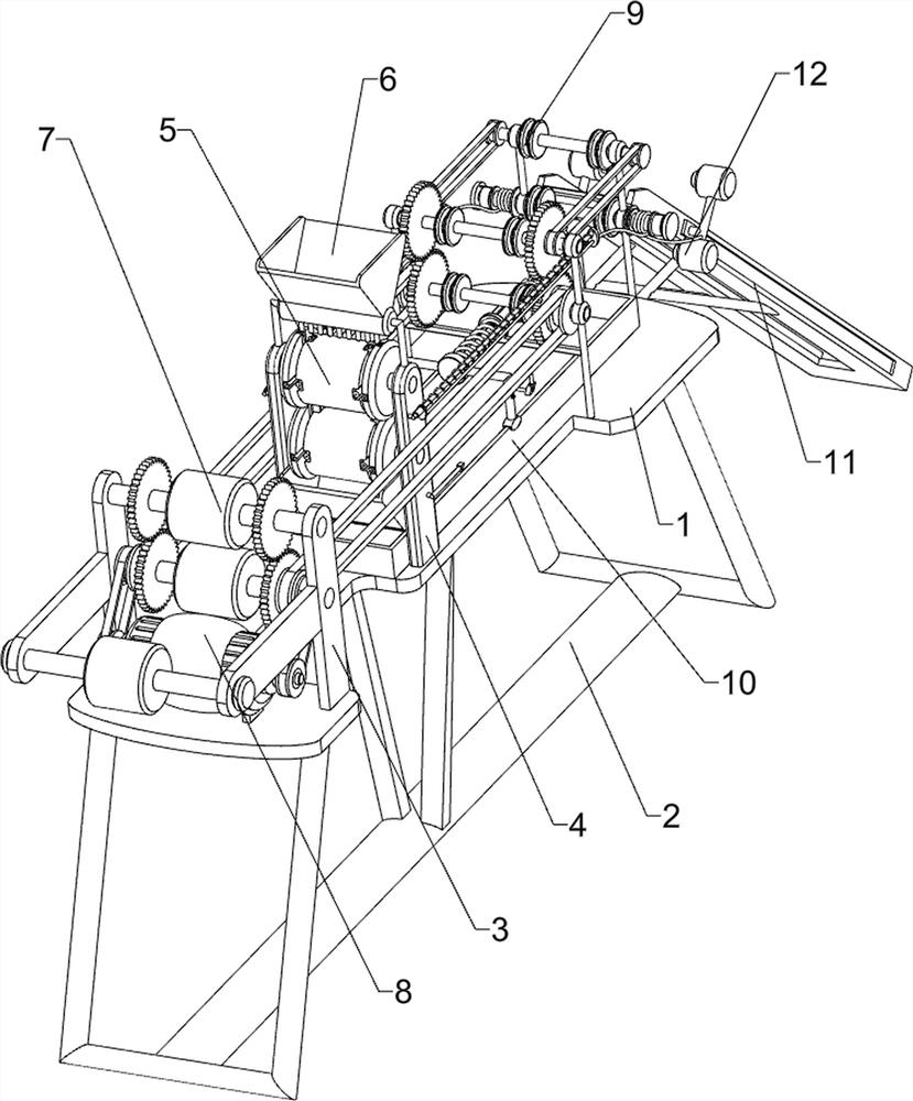
[0029] An I-beam uniform painting equipment, such as Figure 1-2 As shown, it includes a mounting plate 1, a support rod 2, a first side plate 3 and a second side plate 4, the lower part of the mounting plate 1 is connected with a support rod 2, and the left and right sides of the front side of the top of the mounting plate 1 are connected with a first side plate 2. The side plate 3, the left and right sides of the middle of the top of the mounting plate 1 are connected with a second side plate 4, and also includes a paint brushing device 5, a blanking device 6, a transmission device 7 and a driving device 8. The second side plate 4 is provided with There are a paint brushing device 5 and a feeding device 6 , a transmission device 7 is arranged on the first side plate 3 , and a driving device 8 is arranged on the mounting plate 1 , and the driving device 8 is connected with the transmission device 7 by transmission.
[0030] The paint brushing device 5 includes a brush roller ...
Embodiment 2
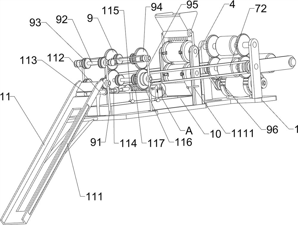
[0036] On the basis of Example 1, as image 3 As shown, a guide device 9 is also included. The guide device 9 includes a first vertical rod 91, a connecting shaft 92, a guide wheel 93, a connecting gear 94, a second vertical rod 95 and a belt drive group 96. The rear side of the top of the mounting plate 1 The left and right sides are connected with first poles 91, the tops of the mounting plates 1 on the front side of the two first poles 91 are connected with second poles 95, between the two first poles 91 and the two second poles Two connecting shafts 92 are rotatably connected between the vertical rods 95. The two connecting shafts 92 are arranged up and down. The two connecting shafts 92 above are connected by pulleys and belt drives. Both sides of the connecting shafts 92 are connected with guide wheels 93. , the two connecting shafts 92 on the front side are connected with connecting gears 94 on both sides, the connecting gears 94 on the two connecting shafts 92 are mesh...
Embodiment 3
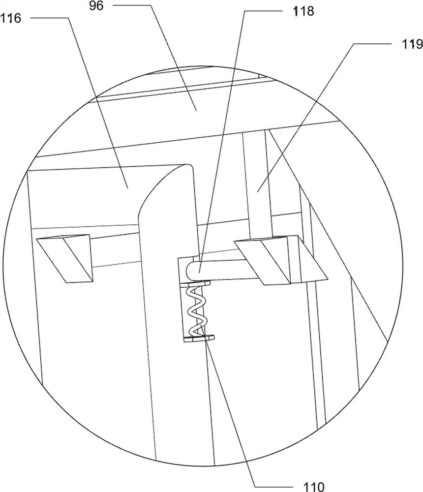
[0041] On the basis of Example 2, as Figure 3-4 As shown, it also includes a pushing device 11. The pushing device 11 includes a sliding frame 111, a sliding sleeve 112, a T-shaped push rod 113, a return spring 114, a sleeve 115, a sliding connecting plate 116, a pressure spring 117, and a wedge-shaped slider 118. , clamping rod 119 and cross rod 1111, the rear side of the mounting plate 1 is connected with a sliding frame 111, the top rear side of the mounting plate 1 is connected with a sliding sleeve 112, and the sliding sleeve 112 is slidably connected with a T-shaped push rod 113, and the T-shaped push rod 113 can extend into the sliding frame 111, a return spring 114 is connected between the sliding sleeve 112 and the T-shaped push rod 113, a sleeve 115 is connected between the lower parts of the two second vertical rods 95, and the sleeve 115 and the T-shaped push rod 113 Sliding fit, a sliding connecting plate 116 is slidably connected to the material receiving frame ...
PUM
 Abstract
Description
Claims
Application Information
 - R&D
- Intellectual Property
- Life Sciences
- Materials
- Tech Scout
- Unparalleled Data Quality
- Higher Quality Content
- 60% Fewer Hallucinations
Browse by: Latest US Patents, China's latest patents, Technical Efficacy Thesaurus, Application Domain, Technology Topic, Popular Technical Reports.
© 2025 PatSnap. All rights reserved.Legal|Privacy policy|Modern Slavery Act Transparency Statement|Sitemap|About US| Contact US: help@patsnap.com