Vane pump rotor clamping tool and method for machining vane pump rotor equally-divided grooves

A vane pump and vane groove technology, used in metal processing equipment, manufacturing tools, grinding workpiece supports, etc., can solve the problems of low processing efficiency, cumbersome process content, unable to guarantee accuracy requirements, etc., to improve processing efficiency and optimize processing. Craftsmanship, the effect of reducing the workload of the fitter

Pending Publication Date: 2022-05-27
SHANXI PINGYANG IND MACHINERY
View PDF10 Cites 0 Cited by
  • Summary
  • Abstract
  • Description
  • Claims
  • Application Information

AI Technical Summary

Problems solved by technology

For some blade rotors with high precision requirements, the groove width symmetry is 0.02mm, the parallelism is 0.008mm, and the roughness is 0.2. One-time forming grinding of CBN grinding wheel cannot guarantee its higher precision requirements.
The traditional grinding method is to complete the rough and fine grinding on the horizontal axis rectangular surface grinder (MM7112), and then the fitter will form the final size through manual rough and fine grinding to ensure its high precision requirements. The process content is cumbersome and the processing efficiency is high. lower

Method used


Image

  • Vane pump rotor clamping tool and method for machining vane pump rotor equally-divided grooves
  • Vane pump rotor clamping tool and method for machining vane pump rotor equally-divided grooves
  • Vane pump rotor clamping tool and method for machining vane pump rotor equally-divided grooves

Examples


Embodiment 1

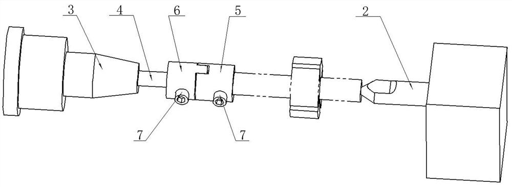
[0020] like image 3 , 4 As shown, a vane pump rotor clamping tool includes a clamp assembly; the clamp assembly includes a first clamp 5 and a second clamp 6; the first and second clamps are sleeves through the center Cylinder structure, the first and second clamps have top screw holes connecting the inside and outside of the clamp, and the top screw holes are equipped with top screws 7; the first and second clamps are connected by a mortise and tenon structure. Interconnected; also includes the tailstock tip mounted on the end of the grinder tailstock. like Figure 4 It can be seen in the figure that the top of the main shaft presses against the left end face of the rotor of the vane pump. The first clamp is located on the outer circumference of the left end of the rotor of the vane pump and is fastened by a top screw; the second clamp is located on the outer circumference of the top of the main shaft and is fastened by a top screw.

Embodiment 2

[0022] like image 3 As shown, one end port of the first clamp 5 is provided with at least one pair of grooves whose slotting direction is parallel to the axial direction of the clamp, and one end port of the second clamp 6 has at least one pair of protrusions extending along the axial direction of the clamp; The first and second clips are connected through grooves and protrusions. This structure can effectively transmit torque, and the disassembly and connection are very convenient and fast.

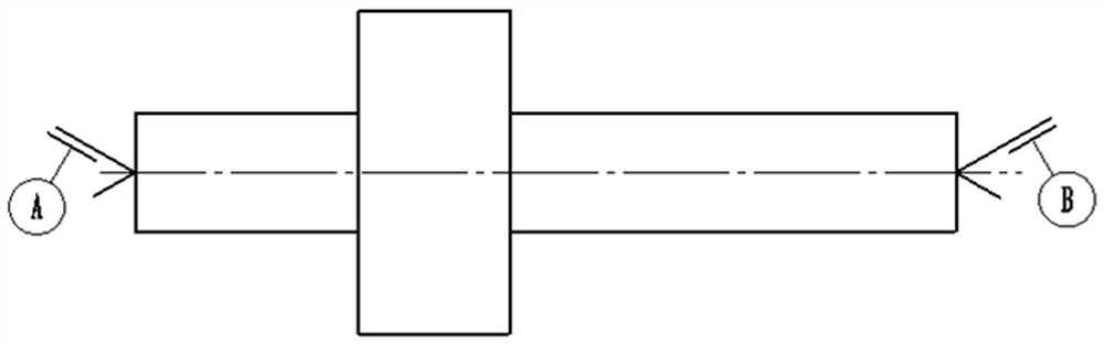
[0023] A product rotor (such as figure 1 , 2 shown), the material is stainless steel 0Cr17NiCu4Nb, the number of blade grooves is 4, the groove width is 4+0.018 0, the groove width symmetry is 0.02mm, the parallelism is 0.008mm, the roughness is 0.2, and the angle size is 90°±3′.

[0024] The selected processing technology is: Rough machining of the blade groove → rough grinding of the blade groove → fine grinding of one side of the blade groove → fine grinding of the other side of t...


PUM

PropertyMeasurementUnit
Parallelismaaaaaaaaaa

Abstract

The invention belongs to the technical field of machine manufacturing, and particularly relates to a vane pump rotor clamping tool and a method for machining vane pump rotor equally-divided grooves. A vane pump rotor clamping tool comprises a clamping hoop assembly. The clamping hoop assembly comprises a first clamping hoop and a second clamping hoop; the first clamp hoop and the second clamp hoop are of sleeve structures with through centers, jackscrew holes communicated with the inside and the outside of the clamp hoops are formed in the side walls of the first clamp hoop and the second clamp hoop, and jackscrews are arranged in the jackscrew holes; the first clamping hoop and the second clamping hoop are connected with each other through a mortise and tenon joint structure. A clamping and positioning device is designed, grinding machining of all blade grooves is completed through one-time clamping, accumulative errors caused by multiple times of clamping are reduced, and the product quality is improved by one precision level; the machining process is optimized, the machining precision requirement is met through precision equipment, the workload of bench workers is reduced, and the machining efficiency is improved; grinding wheel parameters and grinding parameters are determined, the precision requirement is met, meanwhile, the working efficiency is improved to the maximum extent, and batch production is achieved.

Description

technical field [0001] The invention belongs to the technical field of mechanical manufacturing and relates to the technical problem of high-efficiency machining of vane pump rotor equal slots, in particular to a vane pump rotor clamping tool and a method for machining vane pump rotor equal slots. Background technique [0002] The vane pump rotor includes a vane pump rotor body with stepped shafts at both ends. The vane pump rotor body is provided with vane grooves in the radial direction. It is characterized in that the vane grooves are evenly arranged on the outer circle of the vane pump rotor body. On the top, there are a plurality of slots radially formed and has a disc-shaped rotor for vane pumps. When the rotor rotates, the top of the vane is tightly attached to the inner surface of the pump casing, and a sealed working chamber is formed between the pump casing, pump cover, rotor, blade, pressure plate, and wear-resistant plate. As the rotor rotates, the volume of the ...

Claims


Application Information

Patent Timeline
IPC IPC(8): B24B19/02B24B41/06
CPCB24B19/02B24B41/06Y02E10/20
Inventor 陈凯文军赵怀德董鹏杨言高绍喜
Owner SHANXI PINGYANG IND MACHINERY
Why Eureka
Try Eureka