Oil slinger of fuel pump

A technology of fuel pump and oil slinger, which is applied to centrifuges and other directions, can solve the problems of fuel pumps colliding with each other, fuel pump bumping, etc., and achieve the effect of avoiding damage.

Pending Publication Date: 2022-05-27
浙江康松动力科技有限公司
View PDF1 Cites 0 Cited by
  • Summary
  • Abstract
  • Description
  • Claims
  • Application Information

AI Technical Summary

Problems solved by technology

[0005] The technical problem to be solved by the present invention is to provide a fuel pump oil thrower for the deficiencies of the above-mentioned prior art, which can limit the position of the fuel pump, and effectively solve the problem that the fuel pump and the drum occur during the working process of the fuel pump oil thrower. Internal bumps or problems with fuel pumps bumping into each other

Method used


Image

  • Oil slinger of fuel pump
  • Oil slinger of fuel pump
  • Oil slinger of fuel pump

Examples


Embodiment Construction

[0038] The technical solutions in the embodiments of the present invention will be clearly and completely described below with reference to the accompanying drawings in the embodiments of the present invention. Obviously, the described embodiments are only a part of the embodiments of the present invention, rather than all the embodiments. Based on the embodiments of the present invention, all other embodiments obtained by those of ordinary skill in the art without creative efforts shall fall within the protection scope of the present invention.

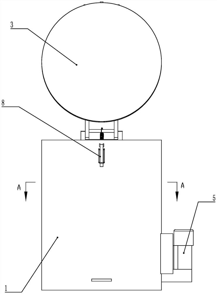
[0039] like Figures 1 to 10 A fuel pump oil slinger comprises an outer barrel 1 with one end open, a drum 2 arranged rotatably in the outer barrel 1, the axis of the drum 2 is arranged parallel to the axis of the outer barrel 1, and the top of the outer barrel 1 is provided with a rotatable drum 2. There is a cover plate 3 hinged with the outer barrel 1, the bottom of the outer barrel 1 is provided with an oil guide pipe 4 that comm...


PUM


Abstract

A fuel pump oil slinger comprises an outer barrel and a roller arranged in the outer barrel, a cover plate hinged to the outer barrel is arranged at the top of the outer barrel, an oil guide pipe and a transmission device are arranged at the bottom of the outer barrel, a plurality of meshes are formed in the roller, a plurality of check blocks are evenly distributed on the inner wall of the roller around the axis of the roller, and the interval between every two adjacent check blocks is a stacking space of a fuel pump. A pressing device is arranged on the check block and comprises a pressing block and a pressing driving mechanism capable of driving the pressing block to limit the fuel pumps, the pressing block is arranged above the stacking space, the pressing driving mechanism is a crank-link mechanism, and when the pressing driving mechanism is located at the dead point position, the pressing block can press the stacked fuel pumps. The problem that the fuel pumps collide with the inner wall of the roller or the fuel pumps collide with one another in the working process of the fuel pump oil slinger can be effectively solved.

Description

technical field [0001] The invention relates to the technical field of oil slingers, in particular to a fuel pump oil slinger. Background technique [0002] fuel pump is car fuel injection system One of the basic components of the fuel tank is located inside the vehicle fuel tank. The fuel pump works when the engine is started and the engine is running. The function of the fuel pump is to suck the fuel from the fuel tank, pressurize it and deliver it to the fuel supply pipe, and burn oil pressure regulator With the establishment of a certain fuel pressure, accidental ignition can be avoided. After the production and installation of the fuel pump, a functional test is required. In order to prevent the metal parts of the fuel pump from rusting, the product is usually immersed in anti-rust oil. Therefore, a large amount of oil remains on the surface of the fuel pump. [0003] However, when the fuel pump needs to be installed, the oil on the surface needs to be removed. In ...

Claims


Application Information

Patent Timeline
Patent Type & Authority Applications(China)
IPC IPC(8): B04B5/00B04B7/00B04B7/06B04B7/02
CPCB04B5/00B04B7/00B04B7/06B04B7/02
Inventor 徐恩慧
Owner 浙江康松动力科技有限公司
Why Eureka
Try Eureka