Eureka AIR delivers breakthrough ideas for toughest innovation challenges, trusted by R&D personnel around the world.

Spraying device for atomizing and oppositely spraying fine powder and tissue fluid

A technology of spraying device and interstitial fluid, which is applied in the direction of feeding device, chemical instrument and method, chemical/physical process, etc., which can solve the problems of waste of material, feeding cone does not have the function of collecting material, tailing backflow, etc.

Active Publication Date: 2022-05-27
深圳本草雾华医药科技有限公司
View PDF7 Cites 0 Cited by
  • Summary
  • Abstract
  • Description
  • Claims
  • Application Information

AI Technical Summary

Problems solved by technology

[0004] However, the technical solution provided by this patent does not have the function of collecting materials for the feed cone. The resistance in the opposite direction, after one injection, a part of the tailings is easy to flow back in the feeding cone, if the tailings are not collected in time, there will be a technical problem of waste of materials

Method used


Image

  • Spraying device for atomizing and oppositely spraying fine powder and tissue fluid
  • Spraying device for atomizing and oppositely spraying fine powder and tissue fluid
  • Spraying device for atomizing and oppositely spraying fine powder and tissue fluid

Examples


Embodiment 1

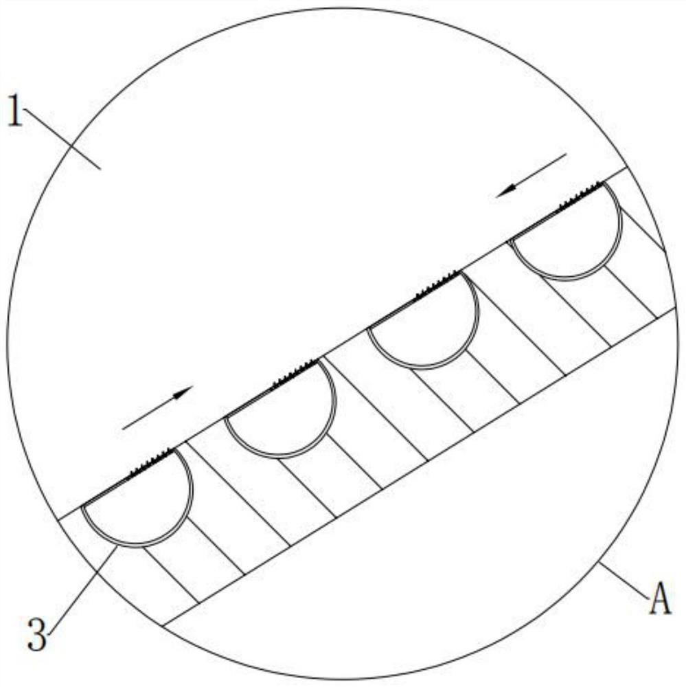
[0037] see Figure 1-4 , in the embodiment of the present invention, a spray device for atomizing and spraying fine powder and tissue fluid, including a feeding cone 1, a feeding cone 2 and an aggregate assembly 3, a feeding cone 1 and a feeding The inner positions of the inner wall of the second cone pipe 2 are all arranged in equal adjacent rows and are embedded with a number of aggregate assemblies 3 that can collect tailings;

[0038] Each set of aggregate assemblies 3 further includes an aggregate shell 301, a guide assembly 302 that can guide the tails into collection, and a pre-collection assembly 303 that can pre-collect the tails;

[0039] Each collecting shell 301 is surrounded and embedded in the inner wall of the feeding cone 1 and the feeding cone 2 in an equal adjacent row;

[0040] A material guide assembly 302 is movably installed at the top position of each collecting shell 301;

[0041] A number of pre-collection assemblies 303 are installed at the right end ...

Embodiment 2

[0046] see Figure 4 The difference between the embodiment of the present invention and the embodiment 1 is that each group of material guide assemblies 302 includes a rotating shaft 302a and a guide plate 302b.

[0047] In the embodiment of the present invention, a rotating shaft 302a is rotatably installed in the middle position of the inner top end of each collecting shell 301 in a front-rear horizontal direction.

[0048] In the embodiment of the present invention, a guide plate 302b is fixed around the outer surface of each rotating shaft 302a, and each guide plate 302b in the feeding cone 1 and the feeding cone 2 is the same as the feeding cone under normal conditions. The inner walls of the first 1 and the feeding cone 2 are on the same plane, and the left and right outer surfaces of each guide plate 302b are tightly magnetically attracted to the top surfaces of the left and right inner walls of each collecting shell 301 under normal conditions. The length of each guid...

Embodiment 3

[0052] see Figure 4-5 The difference between the embodiment of the present invention and the embodiment 1 is that each group of pre-collection components 303 includes a magnetic plate 303a, a rotating rod 303b, an outer plate 303c and an inner plate 303d.

[0053] In the embodiment of the present invention, the position of the right end of each guide plate 302b is equidistantly arranged in a horizontal direction with a plurality of through grooves penetrating up and down, straight left and right arc;

[0054] The through groove that runs through up and down, straight left and right arc here is to facilitate the accumulation of tailings in this through groove and finally fall down into the collecting shell 301 for collection;


PUM


Abstract

The invention provides a spraying device for atomizing and oppositely spraying fine powder and tissue fluid, the spraying device comprises a feeding taper pipe I arranged at the left end, a feeding taper pipe II arranged at the right end and material collecting assemblies, and a plurality of material collecting assemblies capable of collecting tailings are embedded in the inner positions of the inner walls of the feeding taper pipe I and the feeding taper pipe II in an equally adjacent manner in a surrounding manner; each material collecting assembly further comprises a material collecting shell, a material guiding assembly capable of guiding tailings for collection and a pre-collecting assembly capable of pre-collecting the tailings; and the material collecting shells are equally adjacent to one another and are embedded in the inner walls of the first feeding taper pipe and the second feeding taper pipe in a surrounding manner. According to the spraying device for atomizing and oppositely spraying the fine powder and the interstitial fluid, the feeding conical cylinder has a material collecting function, when the fine powder and the interstitial fluid are atomized and oppositely sprayed, due to resistance in the opposite direction, after spraying is completed once, even if part of tailings flow back in the feeding conical cylinder, the tailings can be collected in time, and therefore the fine powder and the interstitial fluid can be conveniently sprayed. And the waste of the materials is prevented.

Description

technical field [0001] The invention relates to the technical field of spraying devices, and more particularly, to a spraying device for atomizing and spraying fine powder and interstitial fluid. Background technique [0002] The gas-liquid mixing effect of the existing injector is not good, and the injection effect is not good at the same time. [0003] In view of the above problems, regarding the technical problem that the ejector injection effect is not good, after a large number of searches, a kind of atomizing injector for hydrogenation reactor with the patent number of CN202021820626.3 was found, which relates to the technical field of chemical equipment, which is It consists of a casing, a feeding cone and a discharging cone. The casing is a hollow cylindrical structure. The interior of the casing is provided with a feeding cone and a discharging cone. The cone end of the feeding cone is connected to the discharging cone. The cone ends are connected, the connection b...

Claims


Application Information

Patent Timeline
Patent Type & Authority Applications(China)
IPC IPC(8): B01J4/00
CPCB01J4/002B01J2204/002Y02P70/10
Inventor 黄晓盼
Owner 深圳本草雾华医药科技有限公司
Why Eureka
Eureka Blog
Learn More