
Controllable intelligent self-adjusting assistance bionic flying wing device

A self-adjusting, power control device technology, applied in aircraft parts, sustainable transportation, climate sustainability, etc., can solve problems such as polluting the environment and wasting energy, and achieve the effect of saving energy and increasing lift

Pending Publication Date: 2022-05-20
WUXI VOCATIONAL & TECHN COLLEGE
View PDF0 Cites 1 Cited by
  • Summary
  • Abstract
  • Description
  • Claims
  • Application Information

AI Technical Summary

Problems solved by technology

At present, there are many kinds of single-person aircraft on the market, such as single-rotor aircraft, dual-rotor aircraft, multi-rotor aircraft and jet aircraft. They mainly use rotors or jets as the main source of lift, which is a waste of energy and pollutes the environment.

Method used


Image

  • Controllable intelligent self-adjusting assistance bionic flying wing device
  • Controllable intelligent self-adjusting assistance bionic flying wing device

Examples


Embodiment

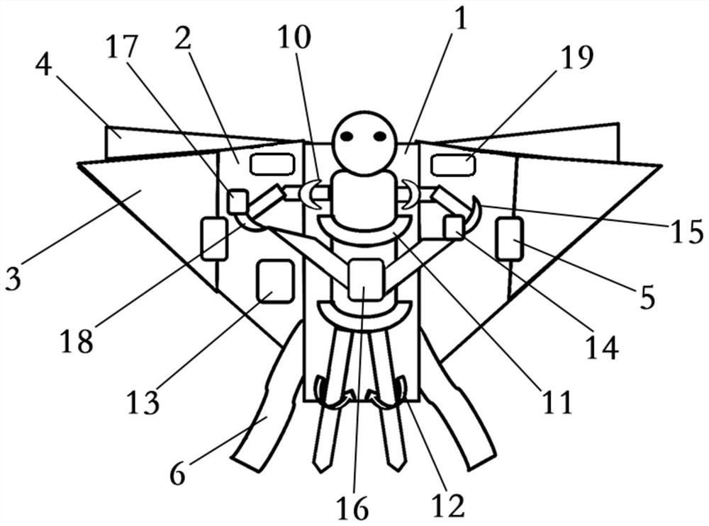
[0028] Such as figure 1 with figure 2 As shown, the present invention provides a controllable intelligent self-adjusting power-assisted bionic flying wing device, comprising:

[0029] The main frame 1 is provided with a human body fixing device for fixing the human body;

[0030] The active wing surface 2 is connected with the main frame 1, and the main frame 1 is provided with a power control device;

[0031] The steering wing 4 is connected with the active wing surface 2, and the main frame 1 is provided with a steering control device;

[0032] The power control device and the steering control device respectively control the flying speed and direction of the flying wing device by controlling the vibration frequency of the active wing surface 2 and the opening and closing of the steering wing 4 .

[0033] Wherein, both the power control device and the steering control device are provided with controllers, which can control the work of the two control devices through manua...

Embodiment approach

[0036] As a preferred embodiment of the present invention, the body immobilization device comprises a fixing belt 10 connected with the main frame 1 for fixing the upper arm, a binding belt 11 for fixing the upper body and an opening for fixing the knee and / or leg hook piece12.

[0037] As a preferred embodiment of the present invention, the tail of the main frame 1 is provided with a phoenix tail ribbon 6 for balancing the movement of the fuselage.

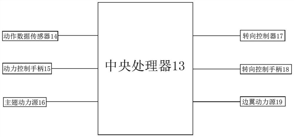
[0038] For controlling the speed when the flying wing advances, the power control device includes a central processing unit 13 and an action data sensor 14 connected with the central processing unit 13, a power control handle 15, a main wing power source 16, and the main wing power source 16 is connected with the The active wing surface 2 is connected, and the central processing unit 13 controls the output power of the main wing power source 16 according to the action data collected by the action data sensor 14 from the power con...


PUM


Abstract

The invention discloses a controllable intelligent self-adjusting power-assisted bionic flying wing device which comprises a main framework provided with a human body fixing device; the driving wing surface is connected with the main framework, and a power control device is arranged on the main framework; the direction control side wings are connected with the driving wing surfaces, and a steering control device is arranged on the main framework; the power control device and the steering control device control the flying speed and the flying direction of the flying wing device by controlling the vibration frequency of the active wing face and opening and closing of the direction control side wings respectively. According to the design, through the main framework and the power control device and the steering control device which are arranged on the main framework, the vibration frequency of the active wing surfaces connected with the main framework and the opening and closing of the direction control side wings are controlled, so that bionic flight actions and power-assisted flight are realized, the energy consumption is reduced, the traffic efficiency is improved, and the road traffic pressure is relieved.

Description

technical field [0001] The invention relates to the technical field of intelligent transportation, in particular to a controllable intelligent self-adjusting power-assisted bionic flying wing device. Background technique [0002] The appearance of single-person aircraft has very important practical significance. The pressure of land transportation is well known, especially in densely populated cities such as Beijing, traffic jams are commonplace, and it is very difficult to solve these problems. Therefore, these problems can be effectively solved by developing some aerodynamic aircraft for single-person flight. At present, there are many kinds of single-person aircraft on the market, such as single-rotor aircraft, dual-rotor aircraft, multi-rotor aircraft and jet aircraft. They mainly use rotors or jets as the main source of lift, which wastes energy and pollutes the environment. [0003] Therefore, there is an urgent need for a flying device that can realize power-assiste...

Claims


Application Information

Patent Timeline
IPC IPC(8): B64C31/024
CPCB64C31/024Y02T50/60
Inventor 王旭王彦彪王志萍
Owner WUXI VOCATIONAL & TECHN COLLEGE
Learn More