High-voltage control box for power electronic converter of new energy automobile
A technology for new energy vehicles and high-voltage control boxes, applied in current collectors, electric vehicles, vehicle components, etc., can solve problems such as bolts vibrating up and down, affecting device fixation, and easy threading of threaded holes to facilitate heat dissipation and increase friction. , good tightening effect
- Summary
- Abstract
- Description
- Claims
- Application Information
AI Technical Summary
Problems solved by technology
Method used
Image
Examples
Embodiment 1
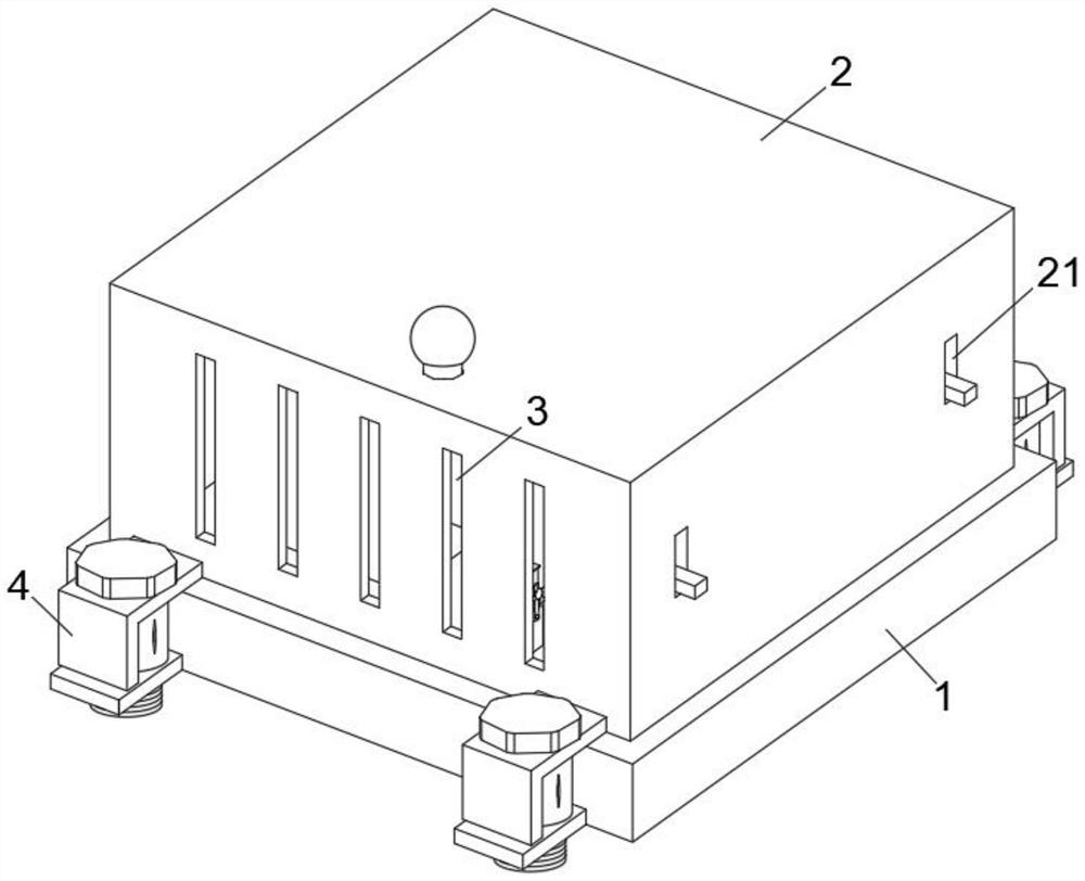
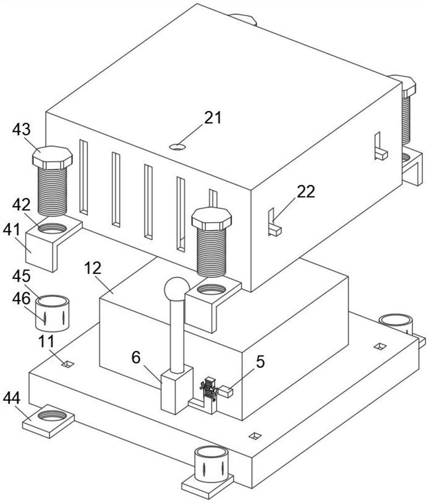
[0030] This embodiment is intended to facilitate the solution of the problem of how to ensure that the bolt 43 does not slip under vibration conditions. Please refer to Figure 1-2 , a new energy vehicle power electronic converter high-voltage control box, including a base 1 and an outer shell 2 arranged on the upper end of the base 1, a built-in component 12 is fixedly installed on the base 1, and a fixing mechanism 4 is fixedly installed on one side of the outer shell 2, The fixing mechanism 4 includes an L-shaped clamping plate 41 fixedly mounted on one end of the outer shell 2 and a connecting plate 44 fixedly mounted on one end of the base 1. Both the L-shaped clamping plate 41 and the connecting plate 44 are provided with threaded holes 42, and the threaded holes 42 internal threads are connected with bolts 43, and a rubber sleeve 45 is fixedly installed on the connecting plate 44. The rubber sleeve 45 communicates with the threaded hole 42. The surface of the rubber slee...
Embodiment 2
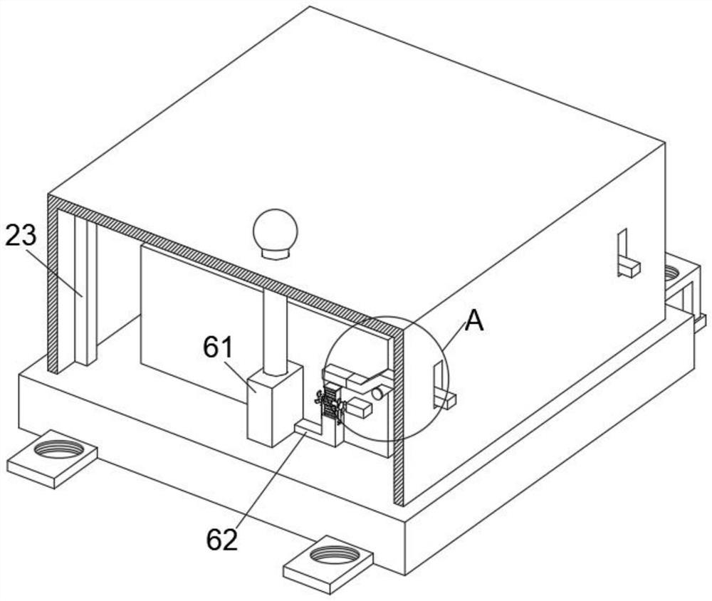
[0036] This embodiment is intended to help solve the problem of how the built-in component 12 automatically breaks the circuit under the condition of high temperature. This embodiment is an improvement made on the basis of Embodiment 1. For details, please refer to Figure 2-5 , the outer wall of the built-in element 12 is provided with a switch mechanism 5, the switch mechanism 5 includes a switch piece 51 interspersed with the escape groove 22 and a first contact block 52 fixedly installed at one end of the switch piece 51, the central part of the switch piece 51 is rotated and installed On the side wall of the built-in element 12, the end of the first contact block 52 away from the switch member 51 is also fixedly installed with an extension rod 53, and the lower end of the first contact block 52 is provided with a second contact block 54, and the second contact block 54 54 is fixedly installed on the built-in element 12 side walls.
[0037] The arc extinguishing mechanism ...
Embodiment 3
[0043] This embodiment is intended to help solve the problem of how to quickly dissipate heat in a high-temperature environment. This embodiment is an improvement made on the basis of Embodiment 2. For details, please refer to Figure 5 , the side wall of the telescopic push rod 63 is fixedly installed with vertical teeth 65, and a gear 66 is installed on the vertical teeth 65. The central part of the gear 66 is interspersed with a central axis 67, and the end of the central axis 67 away from the gear 66 is fixedly installed with a fan. 68 , the central shaft 67 is sleeved with a fixing piece 69 fixedly connected with the outer wall of the communication pipe 62 .
[0044] There are two groups of central shaft 67 , fan 68 and fixing member 69 , and they are all mirror-image mounted on both ends of gear 66 .
[0045] Under the fixing effect of the fixing member 69, the positions of the gear 66 and the central shaft 67 do not change. When the temperature is high, the telescopic p...
PUM
 Abstract
Description
Claims
Application Information
 - Generate Ideas
- Intellectual Property
- Life Sciences
- Materials
- Tech Scout
- Unparalleled Data Quality
- Higher Quality Content
- 60% Fewer Hallucinations
Browse by: Latest US Patents, China's latest patents, Technical Efficacy Thesaurus, Application Domain, Technology Topic, Popular Technical Reports.
© 2025 PatSnap. All rights reserved.Legal|Privacy policy|Modern Slavery Act Transparency Statement|Sitemap|About US| Contact US: help@patsnap.com


