Eureka AIR delivers breakthrough ideas for toughest innovation challenges, trusted by R&D personnel around the world.

A shrinking mold for an inner slider

A technology of inner sliding block and sliding block, applied in the direction of forming tools, manufacturing tools, household appliances, etc., can solve the problems of out-of-round deformation, misalignment, unclear outline, etc.

Active Publication Date: 2019-11-15
佛山市顺德区和协模具制造有限公司
View PDF5 Cites 0 Cited by
  • Summary
  • Abstract
  • Description
  • Claims
  • Application Information

AI Technical Summary

Problems solved by technology

However, the problem is that when the size of the mold core inside the workpiece matches the size of the workpiece, the workpiece cannot be removed after molding; the size of the mold core is too small, and the mold core and the workpiece are rotated during production on the equipment , the mold core cannot completely position the workpiece, which will cause the workpiece to shake, suddenly left and right, resulting in unstable dimensions of the workpiece after processing, out-of-round deformation, displacement, unclear outline, and high scrap rate.

Method used


Image

  • A shrinking mold for an inner slider
  • A shrinking mold for an inner slider
  • A shrinking mold for an inner slider

Examples


Embodiment Construction

[0039] The present invention will be further described below in conjunction with the accompanying drawings and embodiments.

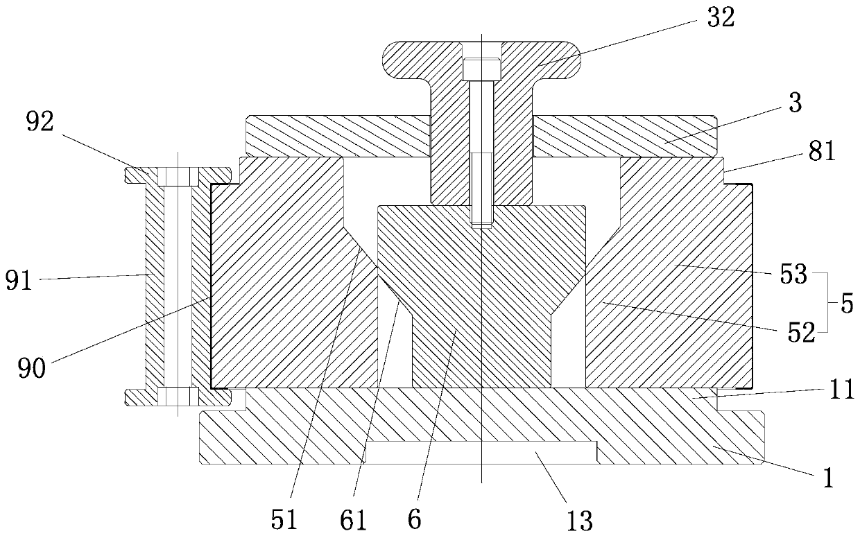
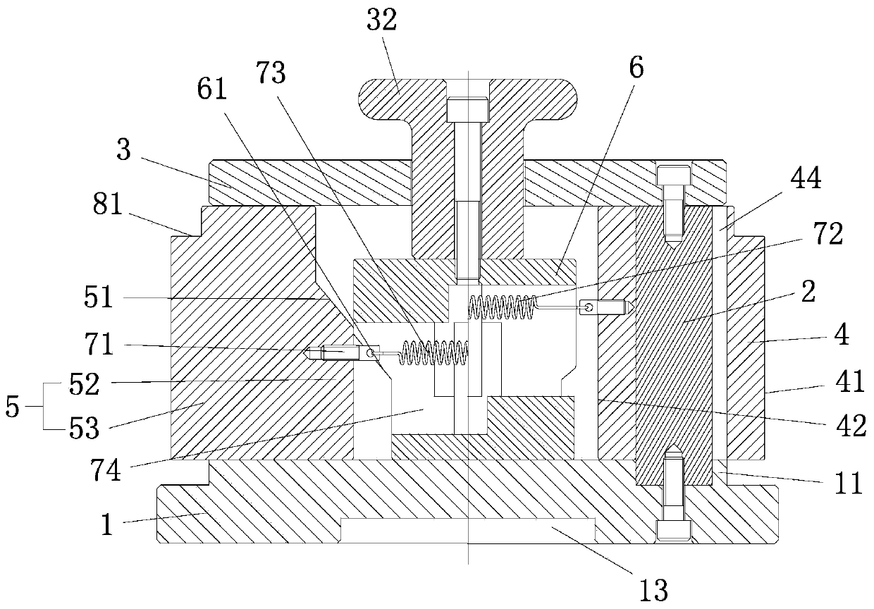
[0040] see Figure 1-Figure 14 , the inner slider shrinkage mold, including a base plate 1, a number of guide blocks 2 uniformly distributed on the base plate 1 along the circumferential direction of the center, and an upper cover plate 3 fixed on the guide block 2, characterized in that the base plate 1 and the upper cover There are several first sliders 4 between the plates 3, a second slider 5 for driving the first slider 4 to slide outward, and a wedge 6 for driving the second slider 5 to slide outward. The block 4 and the second slide block 5 are all located at the periphery of the oblique wedge 6, and a first slide block 4 is set on each guide block 2, the second slide block 5 is located between two adjacent first slide blocks 4, and the first slide block The inner surfaces of the block 4 and the second slide block 5 are connected with reset mech...


PUM


Abstract

Disclosed is an inner sliding block contraction mould. The inner sliding block contraction mould comprises a bottom plate, a plurality of guiding blocks evenly distributed on the bottom plate in the circumferential direction of the center of the bottom plate and an upper cover plate fixed to the guiding blocks. A plurality of first sliding blocks, second sliding blocks used for driving the first sliding blocks to slide towards the outer side and tapered wedges used for driving the second sliding blocks to slide towards the outer side are arranged between the bottom plate and the upper cover plate. The first sliding blocks and the second sliding blocks are located at the peripheries of the tapered wedges. Each first sliding block is mounted on the corresponding guiding block in a sleeving mode. Each second sliding block is located between the two adjacent first sliding blocks. The inner side faces of the first sliding blocks and the second sliding blocks are connected with reset mechanisms used for driving the first sliding blocks and the second sliding blocks to slide towards the center. The inner sliding block contraction mould has the distraction and contraction functions, in theworkpiece forming process, a workpiece is supported and abutted against through the distracted first sliding blocks and the distracted second sliding blocks; and after workpiece forming, the first sliding blocks and the second sliding blocks are contracted, the workpiece is taken out, and machining of inward folding or the pressure level of a round barrel body part is facilitated.

Description

technical field [0001] The invention relates to an inner slider shrinkage mold. Background technique [0002] In the existing technology, such as Figure 9-14 As shown in the figure, most of the circular barrel body workpieces need to be folded inward or graded at both ends due to assembly reasons. When folding or pressing, there must be a structure (core) inside the workpiece to resist it before it can be formed. However, the problem is that when the size of the mold core inside the workpiece matches the size of the workpiece, the workpiece cannot be removed after molding; the size of the mold core is too small, and the mold core and the workpiece are rotated during production on the equipment , The mold core cannot completely position the workpiece, which will cause the workpiece to shake, left and right, resulting in unstable dimensions of the workpiece after processing, out-of-round deformation, displacement, unclear outline, and high scrap rate. [0003] Therefore, fu...

Claims


Application Information

Patent Timeline
Patent Type & Authority Patents(China)
IPC IPC(8): B21D37/10B21D19/06B21D51/18
CPCB21D19/06B21D37/10B21D51/18
Inventor 马春强
Owner 佛山市顺德区和协模具制造有限公司
Why Eureka
Eureka Blog
Learn More