
Simple complex cavity blade core pulling method based on UG modeling

A complex, bladed technology, applied in the field of simple core pulling of complex cavity blades, can solve the problems of structure prone to error, error prone, entity excess, etc., and achieve the effect of simplifying the filling process, less error-prone and improving efficiency.

Pending Publication Date: 2022-05-17
安徽应流航源动力科技有限公司
View PDF0 Cites 0 Cited by
  • Summary
  • Abstract
  • Description
  • Claims
  • Application Information

AI Technical Summary

Problems solved by technology

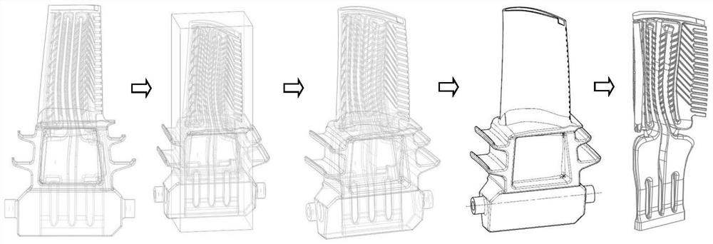
The first is the core-pulling method of entity inclusion, which uses the establishment of a new entity to fill the inner cavity and then pull the core. image 3 , first copy an original cavity blade model, then create a new entity, make the entity contain the cavity area by replacing the surface, trimming the body and other commands, and at the same time ensure that the entity cannot exceed the entire blade area, and combine the entity with the blade Combine to form a cavity-filled model, and finally subtract the copied cavity blades to obtain a complex cavity structure. This method is cumbersome, and it is prone to failure of replacement and deletion, missing filling, and entity exceeding; The second is the core-pulling method of sheet body suture, by creating a new surface and extracting the surface of the inner cavity to suture a new inner cavity entity, as shown in the attached Figure 4 , first extract all the surfaces of all blade structures, keep the surface structure of the complex cavity, make a new surface for the cavity outlet, and finally sew a new cavity entity as a whole. and stitching such a complex structure is extremely prone to errors and cannot be generated
In view of the complex and cumbersome and error-prone points of the original modeling methods, a new core-pulling method is urgently needed to solve these problems

Method used


Image

  • Simple complex cavity blade core pulling method based on UG modeling
  • Simple complex cavity blade core pulling method based on UG modeling
  • Simple complex cavity blade core pulling method based on UG modeling

Examples


Embodiment Construction

[0017] In order to make the technical means, creative features, goals and effects achieved by the present invention easy to understand, the present invention will be further described below in conjunction with specific embodiments.

[0018] Such as figure 1 shown

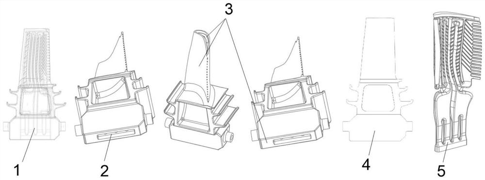
[0019] A simple core-pulling method for blades with complex cavities based on UG modeling, including the following steps:

[0020] S1. Copy a 3D model of a complex cavity blade as the parent model 1 of core pulling, as a backup;

[0021] S2. Delete the area surface of the complex inner cavity of the original complex cavity blade model. In the area surface deletion, firstly select the area surface, the operation is to select any surface of the complex inner cavity as the seed surface 2, and all the surrounding inner cavity The surface is selected as the boundary surface 3. After confirmation, the entire inner cavity area surface is automatically identified, and the identified area surface is deleted through softwa...


PUM


Abstract

The invention discloses a complex cavity blade simple core pulling method based on UG modeling. The method comprises the following steps that S1, a 3D model of a complex cavity blade is copied to serve as a core pulling parent model; s2, deleting a region surface of a complex inner cavity of the original complex cavity blade model to obtain a filled blade profile model; s3, subtracting the copied parent model from the filled blade profile model to obtain an accurate complex inner cavity model, and completing core pulling; according to the method, one-time filling of a complex cavity is achieved through regional surface deletion on a complex cavity blade, the filling process is simplified, core pulling is completed by subtracting duplicated blade model core pulling, core pulling modeling of the cavity blade model which is complex in structure and large in operation amount can be completed accurately in a time-saving mode, and the modeling efficiency is improved. And meanwhile, operation is easy, errors are not prone to occurring, and the efficiency of complex cavity blade core-pulling modeling is greatly improved.

Description

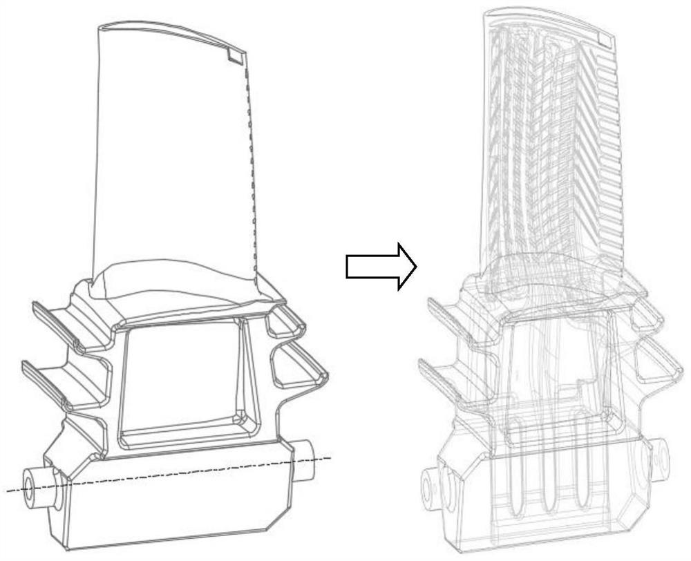
technical field [0001] The invention relates to the technical field of blade core-pulling modeling, in particular to a simple core-pulling method for blades with complex cavities based on UG modeling. Background technique [0002] Precision blades with complex cavities in aerospace are essential and important parts of aerospace engines, among which the spoiler ribs and spoiler columns in the inner cavity of the blades are important guarantees for airflow guidance during engine operation (such as figure 2 shown), but its complex and precise structure has always been a major difficulty and error-prone point in 3D modeling. In the process of engine design and investment casting of such cavity blades, it is often necessary to fill the cavity and core-pulling the 3D model, so as to obtain the solid shape of the cavity for ceramic core manufacturing and analysis, precisely because of the complexity structure, making this type of modeling complex and error-prone. [0003] There a...

Claims


Application Information

Patent Timeline
IPC IPC(8): G06F30/17G06T17/00
CPCG06F30/17G06T17/00
Inventor 李林杜应流程善良罗钢周永芳
Owner 安徽应流航源动力科技有限公司
Learn More