
Tool bit anti-deviation mechanism for cold-rolled stainless steel coiled plate slitting mechanism

A technology of cold-rolling stainless steel and coiling, which is applied in the direction of knives used in shearing machines, metal rolling, and shearing devices, etc., which can solve the trouble of adjusting the gap between the blades, the offset of the shearing position, and the offset of the blade, etc. problem, to achieve the effect of saving time and effort, preventing offset and improving stability

Active Publication Date: 2022-05-17
山东世纪正华金属科技有限公司
View PDF15 Cites 0 Cited by
  • Summary
  • Abstract
  • Description
  • Claims
  • Application Information

AI Technical Summary

Problems solved by technology

[0004] When the cutter head of the slitting machine cuts the cold-rolled stainless steel coil, the cutter head will also be subjected to the back-extrusion force of the steel coil. It will lead to the offset of the cutter head. The gap adjustment of the cutter head of the existing slitting machine is very troublesome, and it is difficult to recover after the offset; and when the cutter head is subjected to the reaction force of the steel coil for a long time, the surface will be curved, resulting in the shear position deviation. shift

Method used


Image

  • Tool bit anti-deviation mechanism for cold-rolled stainless steel coiled plate slitting mechanism
  • Tool bit anti-deviation mechanism for cold-rolled stainless steel coiled plate slitting mechanism
  • Tool bit anti-deviation mechanism for cold-rolled stainless steel coiled plate slitting mechanism

Examples


Embodiment Construction

[0046] The present invention will be described in detail below, and the technical solutions in the embodiments of the present invention will be described clearly and completely. Obviously, the described embodiments are only a part of the embodiments of the present invention, rather than all the embodiments. Based on the embodiments of the present invention, all other embodiments obtained by those of ordinary skill in the art without creative efforts shall fall within the protection scope of the present invention.

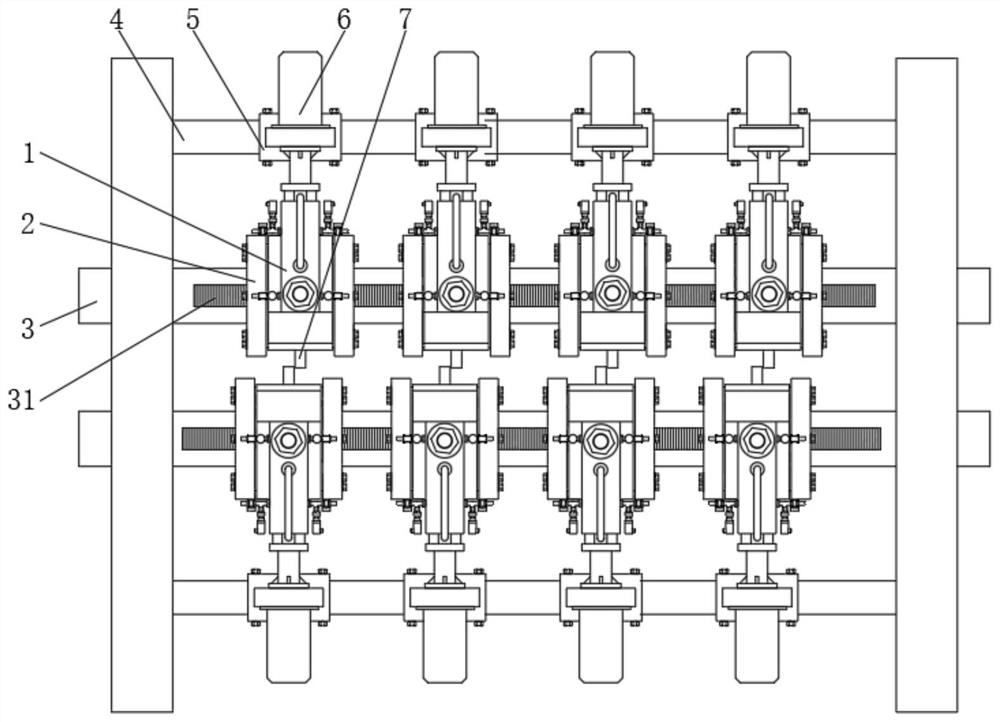
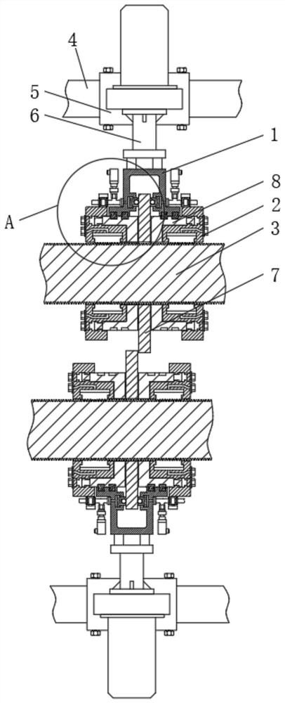
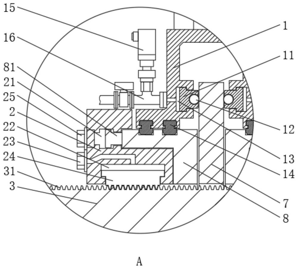
[0047] The present invention provides a cutter head anti-deviation mechanism for a cold-rolled stainless steel coil slitting mechanism through improvement, such as Figure 1-Figure 12 As shown, a cutter head anti-deviation mechanism for a cold-rolled stainless steel coil slitting mechanism includes two cutter shafts 3 distributed in parallel up and down, and a number of disc cutter heads 7 are arranged on the two cutter shafts Two sides of the disc cutter head 7 are s...


PUM


Abstract

The invention relates to the technical field of cold-rolled stainless steel coiled plates, in particular to a tool bit deviation preventing mechanism for a cold-rolled stainless steel coiled plate slitting mechanism, which comprises two tool shafts distributed in parallel up and down, a plurality of disc tool bits are arranged on the two tool shafts, and inner jacket rings are symmetrically arranged on two sides of each disc tool bit. An outer clamping sleeve ring is arranged on the side, away from the disc cutter head, of the inner clamping sleeve ring in a supporting mode and fixedly connected with the cutter shaft in a matched mode. A cutter clamping cover covers one side of the disc cutter head, the cutter clamping cover is connected with the rack, a first rolling supporting body and a second rolling supporting body are arranged on the two sides of the cutter clamping cover, and the first rolling supporting body and the second rolling supporting body on the two sides of the cutter clamping cover are supported on the two sides of the disc cutter head in a rolling mode; the inner clamping sleeve ring and the outer clamping sleeve ring can be used for clamping the disc tool bit together, clamping is more stable, and the anti-deviation purpose is achieved.

Description

technical field [0001] The invention relates to the technical field of cold-rolled stainless steel coils, in particular to a cutter head anti-deviation mechanism for a cold-rolled stainless steel coil longitudinal shearing mechanism. Background technique [0002] Stainless steel coils are divided into austenite, ferrite, martensite, dual-phase (ferrite-austenite) stainless steel cold-rolled coils and stainless steel hot-rolled coils, which are often used in the steel industry and are different from hot-rolled coils. Cold-rolled stainless steel coil refers to a steel strip that is directly rolled into a certain thickness with a roll at room temperature and rolled into a whole coil by a coiler. Compared with hot-rolled coils, cold-rolled coils have a brighter surface and higher finish. [0003] The existing patent technology has the following problems: [0004] When the cutter head of the slitting machine cuts the cold-rolled stainless steel coil, the cutter head will also be...

Claims


Application Information

Patent Timeline
Patent Type & Authority Applications(China)
IPC IPC(8): B23D19/06B23D19/08B23D35/00B23Q11/10B21B15/00
CPCB23D19/06B23D19/08B23D35/007B23D35/004B23Q11/10B21B15/0007B21B2015/0021Y02P70/10
Inventor 王华梁超孙成言衣明宪
Owner 山东世纪正华金属科技有限公司
Learn More