Special-shaped part bending die and control method

A technology for bending molds and special-shaped parts, which is applied in the field of bending mold technology and equipment, can solve the problems of time-consuming and laborious, torn bending materials, and unusable whole sheets, etc., and achieves simple and convenient operation and control, small error in finished product specifications, The effect of reducing the chance of tearing

Pending Publication Date: 2022-05-17
深圳市泰能特模具技术有限公司
View PDF0 Cites 0 Cited by
  • Summary
  • Abstract
  • Description
  • Claims
  • Application Information

AI Technical Summary

Problems solved by technology

[0003] The molds made during the large-scale production of special-shaped parts can generally only be used on the same specification of different-shaped parts, the mold cannot be adjusted, and ordinary dies can only be replaced
For some heterogeneous parts of the sheet, the distance between the bending points on the sheet is set according to the situation, as shown in the attached Figure 13 As shown, there are two first bending surfaces 802 and second bending surfaces 803 with different orientations on the bending material 801, and the distance between the two surfaces is based on the influence of use, production materials, etc., to produce such heterogeneous parts , Traditionally, one side is usually bent first, and then turned over to make the other side. This production method is time-consuming and laborious, and requires precise positioning of the distance for the second bending. The bending equipment needs to take into account the first One-time bending surface; or bending two sides of the bending material at the same time, but this method will cause the problem of tearing of the bending material, and as long as one tear occurs in this sheet material, it will cause the whole Zhang is not available, so the yield rate is not high

Method used


Image

  • Special-shaped part bending die and control method
  • Special-shaped part bending die and control method
  • Special-shaped part bending die and control method

Examples


Embodiment Construction

[0077] In order to make the above objects, features and advantages of the present invention more comprehensible, specific implementations of the present invention will be described in detail below in conjunction with the accompanying drawings. In the following description, numerous specific details are set forth in order to provide a thorough understanding of the present invention. However, the present invention can be implemented in many other ways different from this description, and those skilled in the art can make similar improvements without departing from the connotation of the present invention, so the present invention is not limited by the specific embodiments disclosed below.

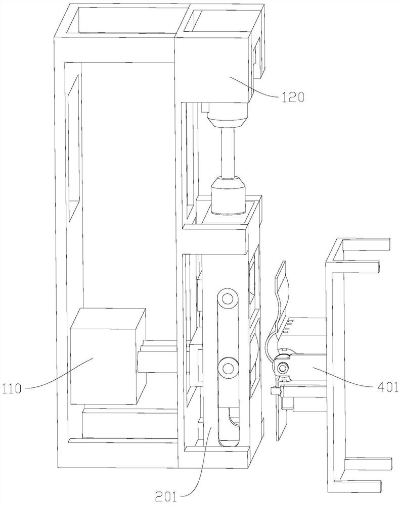
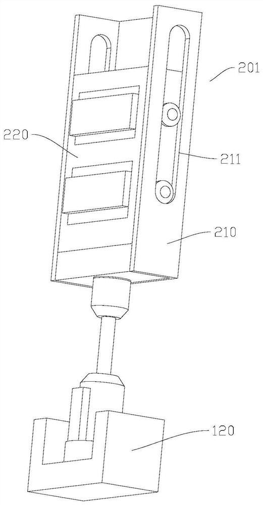
[0078] Such as Figure 1-Figure 12 As shown, the present invention discloses a bending mold for special-shaped parts, which includes: a first bracket 101, on which a hydraulic device 110, a linear drive device 120, and an upper mold assembly 201 are installed. The device 110 and the linear d...


PUM


Abstract

The invention discloses a special-shaped part bending die and a control method, the special-shaped part bending die comprises a first support, the first support is provided with a hydraulic device, a linear driving device and an upper die assembly, and the hydraulic device and the linear driving device are used for driving the upper die assembly to work; the lower die assembly is arranged on the side right opposite to the upper die assembly, and other devices and structures are arranged on the lower die assembly; and the corresponding control method is matched, so that the materials can be conveniently and efficiently bent, and meanwhile, the production specification, particularly the bending distance, can be conveniently adjusted.

Description

technical field [0001] The invention relates to the technical equipment field of bending dies, in particular to a special-shaped bending die. Background technique [0002] In order to meet the specific structure of the internal and external shapes of some products, designers often design various heterosexual parts with different shapes. [0003] The molds made during the large-scale production of special-shaped parts can only be used on the same specification of the same-shaped parts. The mold cannot be adjusted, and ordinary dies can only be replaced. For some heterogeneous parts of the sheet, the distance between the bending points on the sheet is set according to the situation, as shown in the attached Figure 13 As shown, there are two first bending surfaces 802 and second bending surfaces 803 with different orientations on the bending material 801, and the distance between the two surfaces is based on the influence of use, production materials, etc., to produce such het...

Claims


Application Information

Patent Timeline
Patent Type & Authority Applications(China)
IPC IPC(8): B21D5/02B21D43/00B21D37/04B21C51/00
CPCB21D5/0209B21D5/0227B21D43/003B21D5/002B21D37/04B21C51/00
Inventor 王帅恒
Owner 深圳市泰能特模具技术有限公司
Why Eureka
Try Eureka