A processing method for steel cage of long helical bored cast-in-place pile

A technology of long helical drilling and processing methods, applied in the direction of wire processing, wire mesh, household appliances, etc., can solve problems such as lack of specifications

Active Publication Date: 2021-09-03
YUNNAN CONSTR INVESTMENT FIRST SURVEY & DESIGN CO LTD
View PDF6 Cites 0 Cited by
  • Summary
  • Abstract
  • Description
  • Claims
  • Application Information

AI Technical Summary

Problems solved by technology

[0004] Therefore, it is particularly important to make the reinforcement cage for long spiral bored piles. In addition to meeting the design and relevant acceptance specifications, the bottom 3-5m of the reinforcement cage should be made into a pointed cone, and there should be a reinforced structure to ensure vibration. The force is effectively transmitted to the bottom of the reinforcement cage; at present, there is no convenient and fast method suitable for making long spiral drilled cast-in-place pile reinforcement cages, especially the lack of standardized and fast methods for making the bottom of the reinforcement cage into a standardized pointed cone

Method used


Image

  • A processing method for steel cage of long helical bored cast-in-place pile
  • A processing method for steel cage of long helical bored cast-in-place pile
  • A processing method for steel cage of long helical bored cast-in-place pile

Examples


Embodiment 1

[0057] Such as Figure 1-6 shown

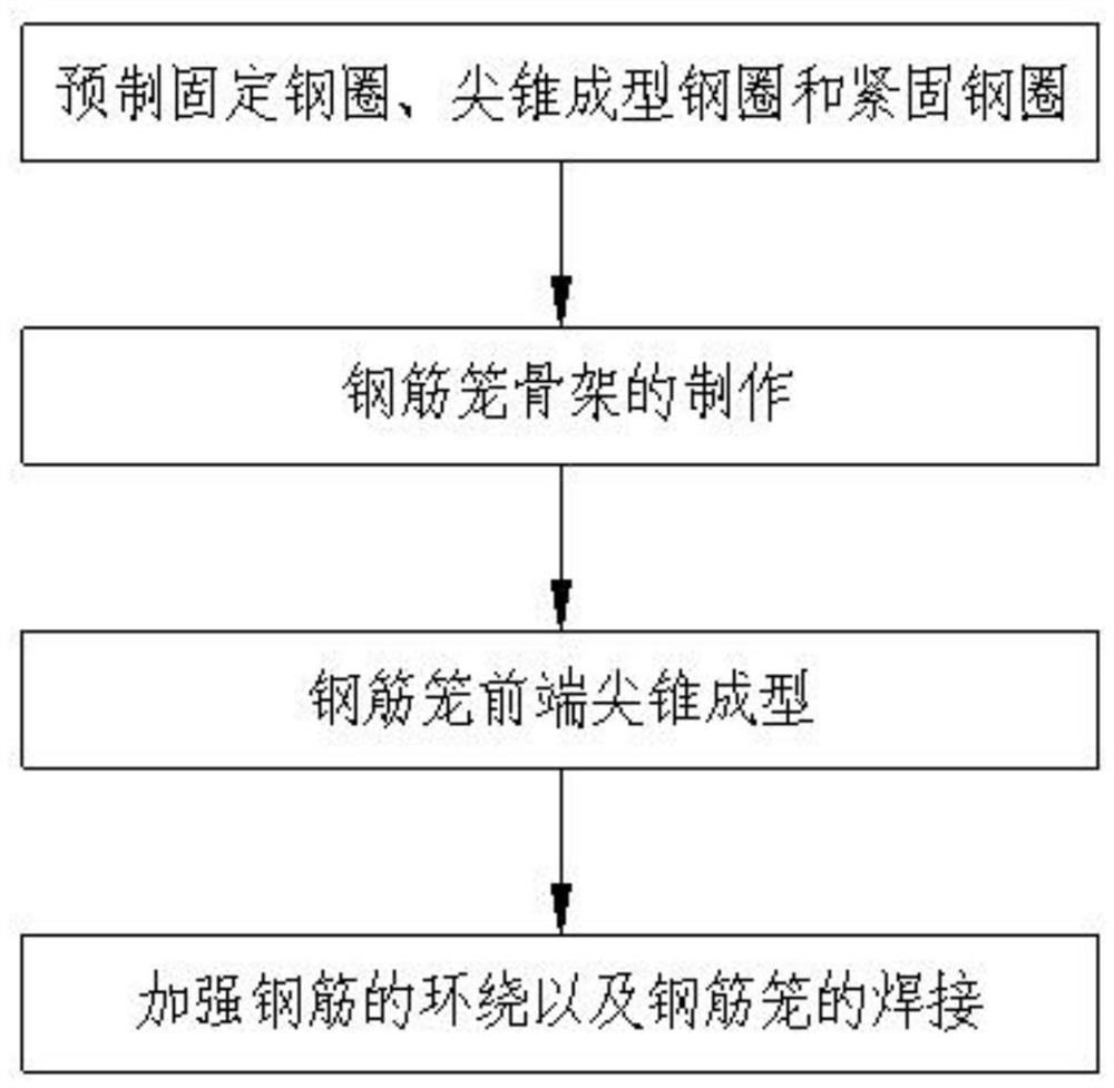
[0058] A method for processing a long helical bored cast-in-situ pile reinforcement cage, comprising the following steps:

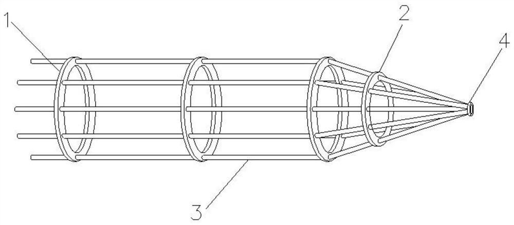
[0059] Step 1. Prefabricated fixed steel ring 1, tapered steel ring 2 and fastening steel ring 4

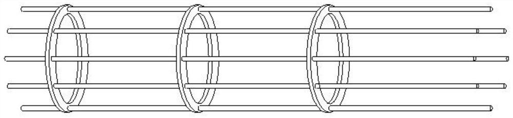
[0060] Make a number of fixed steel rings 1 with the same specifications and uniform through holes around the edge; make at least three tapered steel rings 2 with through holes whose diameters are successively reduced relative to the fixed steel rings 1; make a fastening steel ring Circle 4;

[0061] Evenly distributed through holes are opened in the circumferential direction of the outer edge of the fixed steel ring 1, the diameter of the through holes is larger than the outer diameter of the main reinforcement, and the through holes are spaced at 30° or 45°.

[0062] The axial center position of a fixed steel ring 1 at the front end is welded with a steel pipe coincident with the axial center through the supporting spo...

Embodiment 2

[0078] Application of a method for processing steel cages of long auger bored cast-in-place piles in cast-in-place piles with steel cages inserted after long auger drilled press-filled concrete.

[0079] According to the above operation method, according to the length of the long auger bored cast-in-place pile reinforcement cage, select a suitable fixed steel ring 4 and fastening steel ring 4 for production, thereby obtaining a long auger drilled cast-in-place pile reinforcement cage for long auger drilled piles. Application in cast-in-situ pile engineering with reinforced cage inserted after pouring concrete.

[0080] The processing method of the steel cage of the long helical drilled cast-in-place pile of the present invention, through prefabricating the fixed steel ring, the sharp cone forming steel ring and the fastening steel ring; the making of the steel cage skeleton; the sharp cone forming at the front end of the steel cage; Welding of reinforcement cages; Efficient an...


PUM


Abstract

The invention discloses a processing method for a long helical bored cast-in-situ pile reinforcement cage, and relates to the technical field of bored cast-in-situ pile reinforcement cages. The processing method of the steel cage of the long helical bored cast-in-place pile includes: prefabricating a fixed steel ring, a sharp cone-shaped steel ring and a fastening steel ring; making a steel cage skeleton; forming a sharp cone at the front end of the steel cage; Welding of the cage. Efficient and quick production can obtain a long helical bored pile reinforcement cage with a tapered bottom, small specification error, and overall standardization. The formed long auger bored pile reinforcement cage is stable and reliable, and can ensure effective vibration force when placed Conducted to the bottom of the reinforcement cage, it is suitable for the project of inserting the reinforcement cage into the cast-in-place pile after the long auger drilling presses the concrete.

Description

technical field [0001] The invention relates to the technical field of reinforced cages for bored cast-in-situ piles, in particular to a processing method for reinforced cages for long helical drilled cast-in-situ piles. Background technique [0002] Cast-in-situ pile refers to the pile hole formed in the foundation soil by means of mechanical drilling, steel pipe extrusion or manual excavation at the project site, and a pile made by placing a steel cage and pouring concrete in it. According to different hole-forming methods, Cast-in-situ piles can be divided into several categories such as immersed pipe piles, bored piles and bored piles. The main function of the reinforcement cage is the same as that of the vertical reinforcement of the column. It mainly plays a role in tensile strength. The compressive strength of concrete is high but the tensile strength is very low. It acts as a constraint on the concrete of the pile body so that it can bear a certain horizontal force....

Claims


Application Information

Patent Timeline
Patent Type & Authority Patents(China)
IPC IPC(8): B21F27/20
CPCB21F27/20
Inventor 刘军贾荣谷沈家仁刘克文郭光八段志超杨纬卿余建强聂建微陈锦文徐俊波农礼辉
Owner YUNNAN CONSTR INVESTMENT FIRST SURVEY & DESIGN CO LTD
Why Eureka
Try Eureka