
Counter-flow air-air cooling structure for asynchronous motor

A technology for asynchronous motors and cooling structures, which is applied in the direction of cooling/ventilation devices, electromechanical devices, electrical components, etc., and can solve problems such as poor heat dissipation, large wind resistance of air-to-air cooling structures, and large friction losses, so as to solve large wind resistance and reduce air Effects of flow resistance, entrance impact loss, and improvement of heat transfer capacity

Pending Publication Date: 2022-05-13
CRRC XIAN YONGE JIELI WIND ENERGY CO LTD
View PDF9 Cites 0 Cited by
  • Summary
  • Abstract
  • Description
  • Claims
  • Application Information

AI Technical Summary

Problems solved by technology

[0005] The purpose of the present invention is to overcome the above-mentioned shortcomings of the prior art, and provide a counterflow air-to-air cooling structure for asynchronous motors, which reduces the internal friction and pipeline resistance of the motor, realizes the continuity of the cooling medium flow, and solves the existing air-to-air cooling structure. The cooling structure has large wind resistance, large friction loss, and poor heat dissipation effect

Method used


Image

  • Counter-flow air-air cooling structure for asynchronous motor
  • Counter-flow air-air cooling structure for asynchronous motor
  • Counter-flow air-air cooling structure for asynchronous motor

Examples


Embodiment Construction

[0033] Reference will now be made in detail to the exemplary embodiments, examples of which are illustrated in the accompanying drawings. When the following description refers to the accompanying drawings, the same numerals in different drawings refer to the same or similar elements unless otherwise indicated. The implementations described in the following exemplary examples do not represent all implementations consistent with the present invention. Rather, they are merely examples of structures consistent with aspects of the invention as recited in the appended claims.

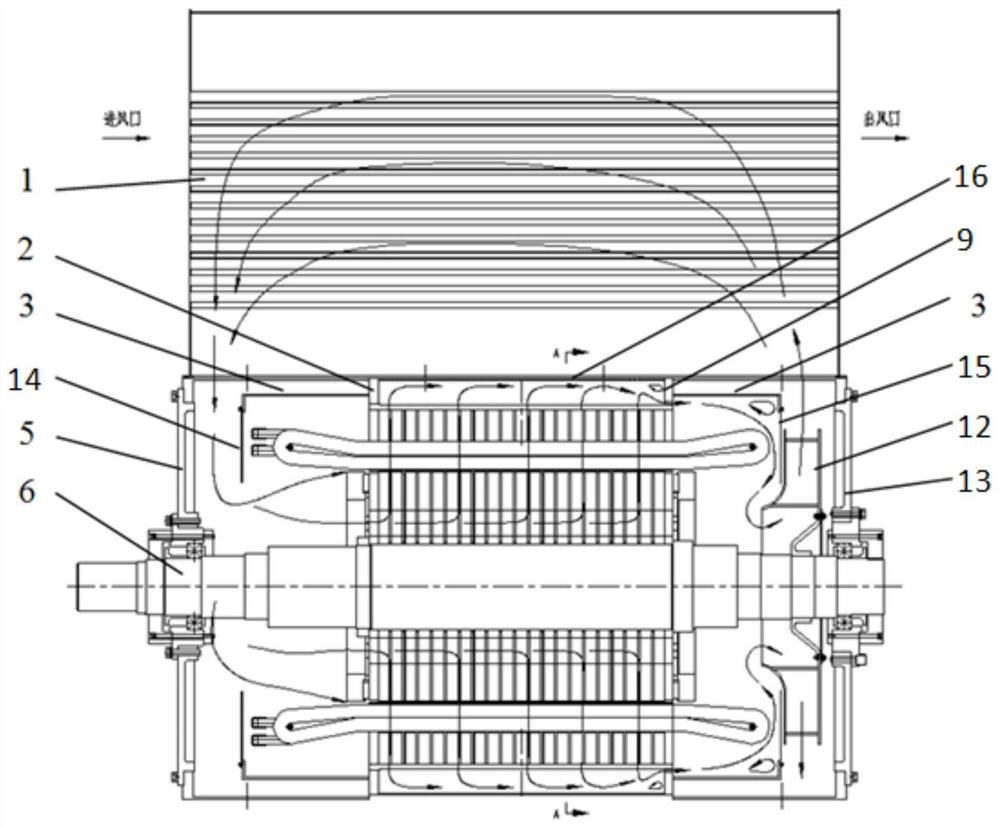
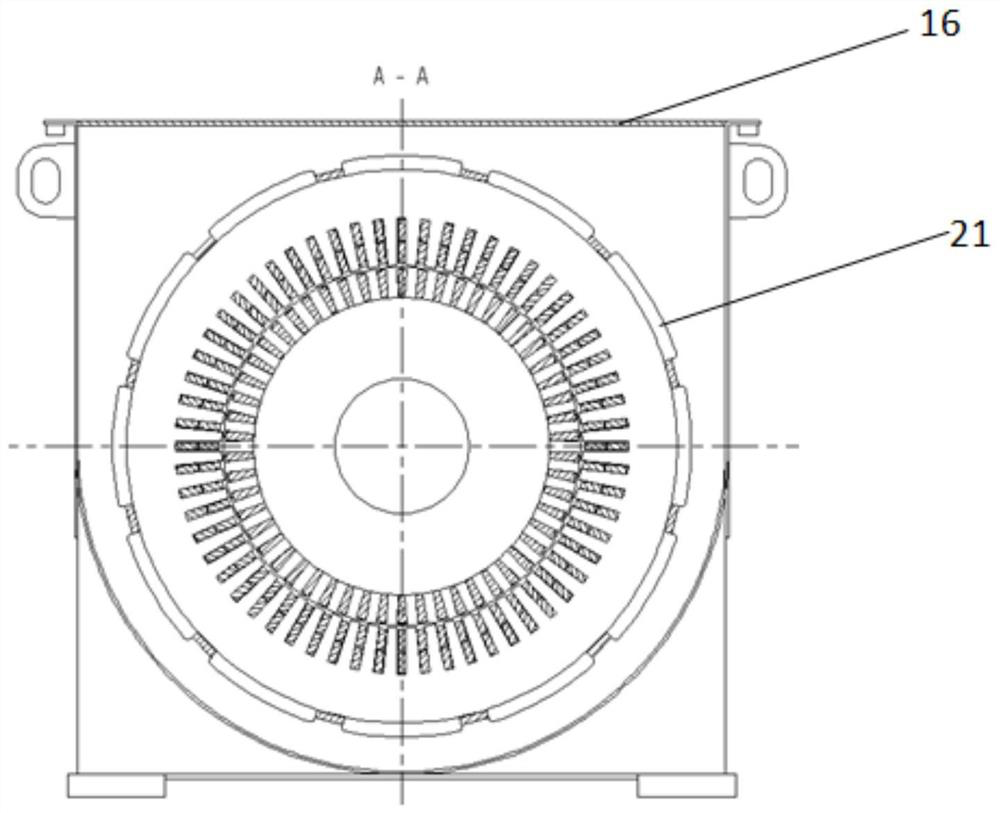
[0034] see Figure 1-2 As shown, the air-to-air cooling motor of the existing hybrid ventilation system has the following disadvantages in its ventilation structure: ①The space above the iron core is small, and the air resistance from the radial air passage of the stator core is relatively large; ②The air just exits the right side of the frame After opening 21 of the ventilation hole of the panel, it is nece...


PUM


Abstract

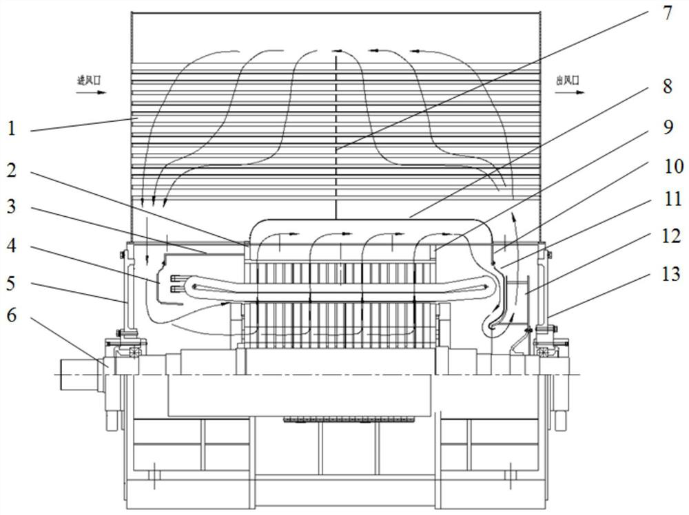
The invention belongs to the technical field of wind driven generators, and relates to a reverse-flow type air-air cooling structure for an asynchronous motor, which is characterized in that by changing a base structure in the motor, a guide plate is designed below a middle heat exchange part in an air-air cooler, and a base baffle or a cylinder structure above a stator iron core is omitted; the first partition plate is additionally arranged between the right center plate and the right end plate of the base, and an air duct connected with the right center plate of the base is omitted. Through the change of the two main structures, the cooling air flow path is changed, and the space between the upper part of the iron core and the air-air cooler is increased, so that the air flow resistance is greatly reduced, and the air flow speed is increased; and the air flowing direction between the upper part of the iron core and the air-air cooler guide plate is opposite to the air flowing direction between the internal pipelines of the air-air cooler, so that a countercurrent effect is achieved, and heat exchange cooling of air is facilitated.

Description

technical field [0001] The invention belongs to the technical field of wind power generators, and relates to a motor cooling structure, in particular to a counterflow air-to-air cooling structure for an asynchronous motor. Background technique [0002] With the development of the large-scale trend of single-unit power in the wind power market and the pressure of the year-by-year reduction of the cost of electricity, modern motors use higher electromagnetic loads to improve the utilization of materials, and the capacity of single-unit motors is increasing day by day. Cooling system to increase its heat dissipation capacity. At present, the air cooling system using air as the cooling medium is most widely used in motor manufacturing. [0003] The air-air cooling motor of the existing hybrid ventilation system has a structure such as Figure 1-2 As shown, the ventilation and cooling circuit includes a primary air path and a secondary air path; among them, the flow path of the ...

Claims


Application Information

Patent Timeline
Patent Type & Authority Applications(China)
IPC IPC(8): H02K9/06
CPCH02K9/06
Inventor 段志强何庆峰程新德刘新峰李新奇
Owner CRRC XIAN YONGE JIELI WIND ENERGY CO LTD
Learn More