Control apparatus for hydraulically operated vehicular transmission

A control method and gearbox technology, applied in the direction of engine control, transmission control, and components with teeth, etc., can solve the problem of insufficient hydraulic pressure increase

Inactive Publication Date: 2004-04-07
HONDA MOTOR CO LTD
View PDF0 Cites 0 Cited by
  • Summary
  • Abstract
  • Description
  • Claims
  • Application Information

AI Technical Summary

Problems solved by technology

Therefore, at low oil temperature, even though the detection value of the engagement pressure detected by the hydraulic pressure detection device has exceeded a predetermined value, the actual hydraulic pressure in the hydraulic engagement element on the engagement side does not increase sufficiently

Method used


Image

  • Control apparatus for hydraulically operated vehicular transmission
  • Control apparatus for hydraulically operated vehicular transmission
  • Control apparatus for hydraulically operated vehicular transmission

Examples


Embodiment Construction

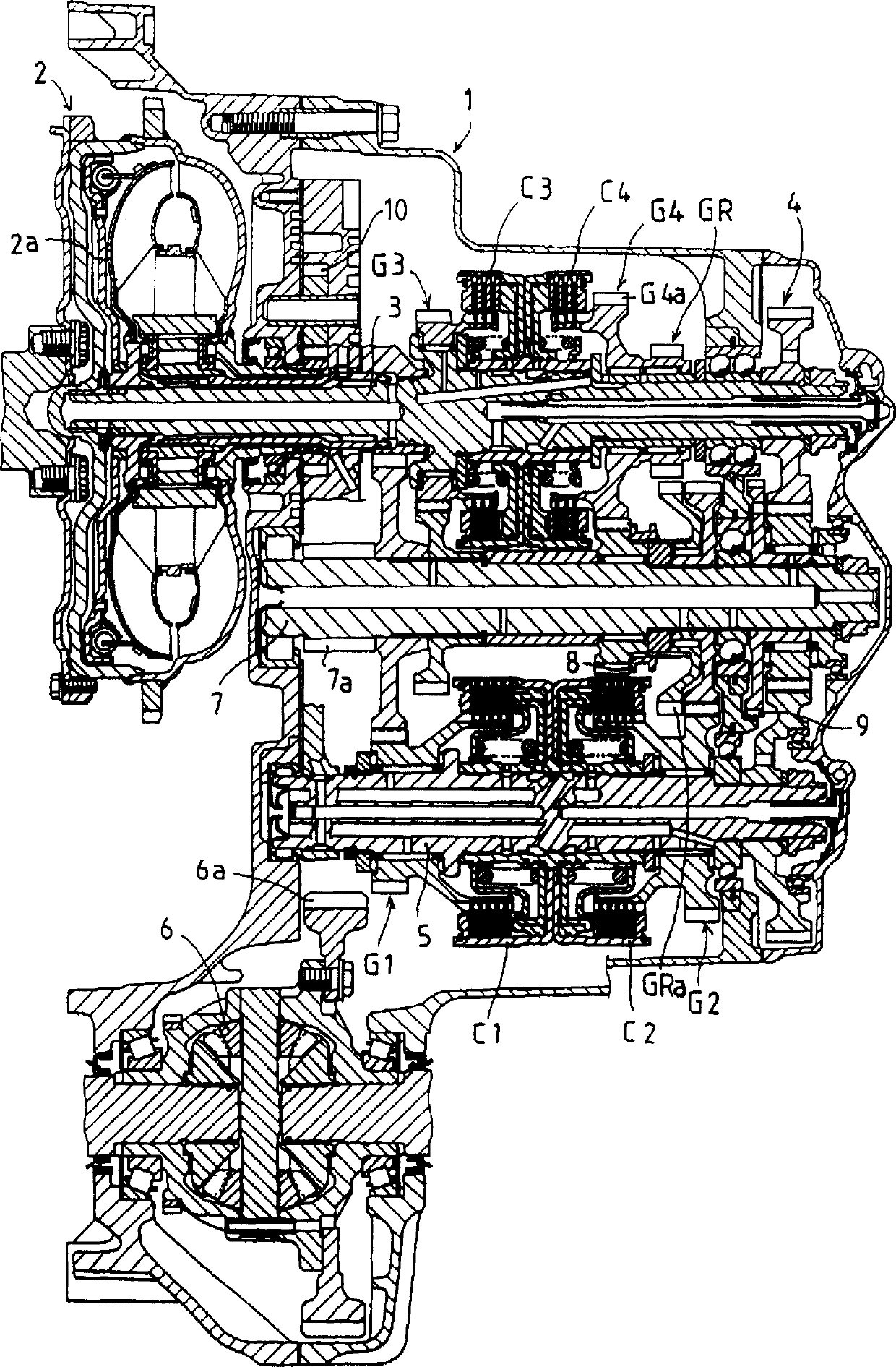
[0023] Referring to FIG. 1, numeral 1 designates a hydraulically operated vehicle transmission for performing speed changes of four forward drive trains and one reverse drive train. The gearbox 1 is equipped with: an input shaft 3, connected to an engine via a torque converter 2; an intermediate shaft 5, always connected to the input shaft 3 via a gear train 4; and an output The shaft 7 has a shaft end output gear 7a meshing with a final gear 6a on a differential 6 connected to drive wheels of a vehicle such as a motor vehicle. In the drawing, the final gear 6a and the output gear 7a are shown separated from each other. This is because the figure is drawn in a developed view, but actually the gears 6a, 7a are meshed with each other.

[0024] A first speed transmission train G1 and a second speed transmission train G2 are provided in parallel between the intermediate shaft 5 and the output shaft 7 . A third-speed gear train G3, a fourth-speed gear train G4, and a reverse gear...


PUM


Abstract

In a control apparatus for a hydraulically operated vehicular transmission (1), the hydraulic pressure of a hydraulic clutch on the engaging side which is engaged at the time of speed changing (engaging pressure) is detected by a hydraulic pressure sensor. When the detected value of the engaging pressure has exceeded a predetermined value, the hydraulic pressure of a hydraulic clutch on the disengaging side to be disengaged at the time of speed changing (disengaging pressure) is reduced to a predetermined low pressure. Even if the detected value of the engaging pressure has exceeded a predetermined value YPC, the decrease in the disengaging pressure down to a predetermined low pressure QUPOFFB is delayed by a predetermined time YTMUP9 at the time of low oil temperature when the detected value of an oil temperature to be detected by an oil temperature sensor (38) is below a predetermined value YTO.

Description

technical field [0001] The present invention relates to a control method for a hydraulically operated vehicle transmission having a plurality of speed stages established by selective operation of a plurality of hydraulically engaging elements. In this specification, the term "vehicle transmission" means a transmission for a vehicle such as a motor vehicle. Background technique [0002] As such a control device, the following one has hitherto been known. That is, by using an electromagnetic proportional valve, the hydraulic pressure (engagement pressure) of the hydraulic engagement element on the engagement side to be engaged when the speed is changed and the hydraulic pressure of the hydraulic engagement element on the disengagement side to be disengaged when the speed is changed are electronically controlled pressure (off pressure). [0003] During speed changes, especially during acceleration, if the disengagement pressure decreases before the engagement pressure has inc...

Claims


Application Information

Patent Timeline
Patent Type & Authority Patents(China)
IPC IPC(8): F16H59/72F16H61/06F16H61/08
CPCY10T477/6939F16H61/061F16H59/72Y10T477/653
Inventor 高松正明宫本修秀斋藤雅秀铃木利行铃木忠裕
Owner HONDA MOTOR CO LTD
Why Eureka
Try Eureka