High-energy light beam energy collecting device in vacuum environment

A technology of vacuum environment and energy collection, which is used in liquid/vacuum degree measurement for liquid tightness, optics, condensing mirror, etc. It can solve problems such as inability to adapt to vacuum environment, solve the problem of recovering beam energy, and overcome inability to adapt to vacuum environment. , the effect of increasing the illuminated area

Pending Publication Date: 2022-05-13
INNOVATION ACAD FOR MICROSATELLITES OF CAS +1
View PDF0 Cites 0 Cited by
  • Summary
  • Abstract
  • Description
  • Claims
  • Application Information

AI Technical Summary

Problems solved by technology

[0003] In view of the fact that the existing high-energy beam collection devices are mostly used for testing under normal pressure conditions and cannot be adapted to vacuum environments, the present invention aims to design a high-energy beam collection device that is suitable for vacuum environments and has a self-cleaning function at the same time, so that high-energy beam generators can be used in vacuum environments. under the test

Method used


Image

  • High-energy light beam energy collecting device in vacuum environment
  • High-energy light beam energy collecting device in vacuum environment
  • High-energy light beam energy collecting device in vacuum environment

Examples


Embodiment Construction

[0026] The present invention will be further described below in conjunction with the accompanying drawings.

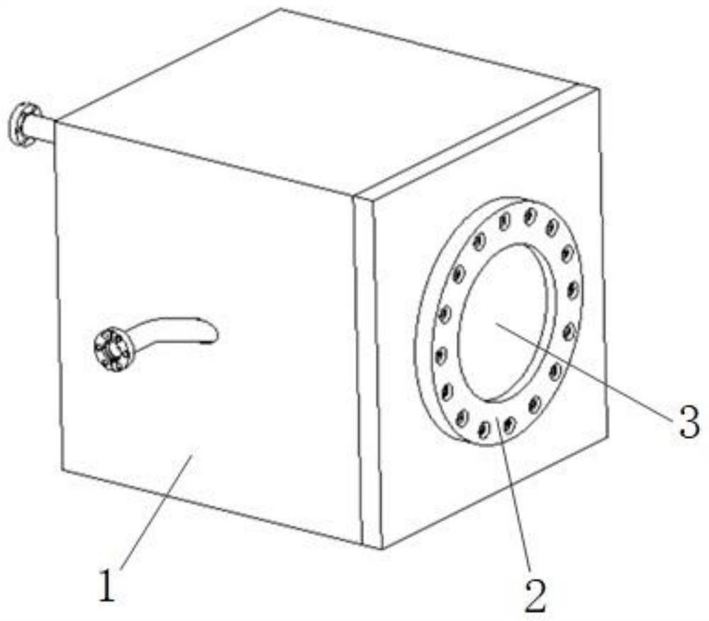
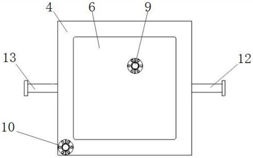
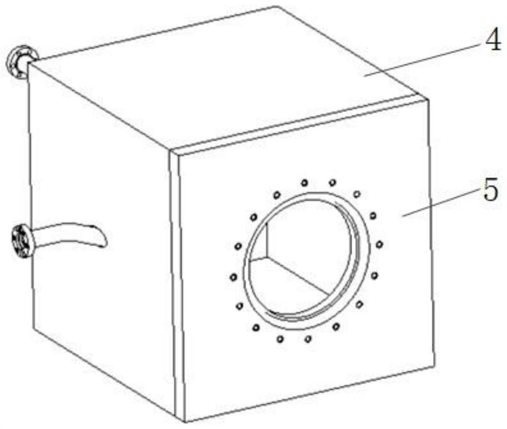
[0027] The high-energy beam energy harvesting device designed in this embodiment is as Figure 1-6 As shown, the device is composed of a cavity assembly 1, a gland 2 and a glass 3, wherein the cavity assembly 1 is composed of a cavity 4, a rear cover 6, a front cover 5, a liquid inlet 9, a liquid outlet 10, an inlet Gas outlet pipeline 12, gas outlet pipeline 13 are formed.

[0028] The front side of the cavity 4 is open, and a front cover 5 is arranged at the front side opening of the cavity 4 . The middle opening of the front cover 5 is provided with a glass 3 at the middle opening of the front cover 5 . The glass 3 is pressed and fixed by the gland 2 .

[0029] An air inlet 7 and an air outlet 8 are respectively opened on the left and right sides of the cavity 4, and both the air inlet 7 and the air outlet 8 are inclined toward the glass. An air inlet pipeline 1...


PUM


Abstract

The invention discloses a high-energy light beam energy collection device in a vacuum environment. A cavity assembly comprises a cavity, an opening is formed in the front side of the cavity, and a front cover is arranged at the opening in the front side of the cavity; glass is arranged at the opening in the middle of the front cover; an air inlet and an air outlet are formed in the left side and the right side of the cavity respectively, an air inlet pipeline is installed in the air inlet, and an air outlet pipeline is installed in the air outlet. The back face of the cavity is a conical face protruding forwards, a rear cover is arranged at the bottom of the conical face, a back face liquid flow channel is formed between the rear cover and the back face of the conical face, and a liquid inlet is formed in the rear cover; liquid runners are arranged on the upper, lower, left and right side surfaces of the cavity, and a liquid outlet is formed in the tail end of the liquid runner on one of the upper, lower, left and right side surfaces; the device adapts to a high-energy light beam collecting device in a vacuum environment, has a self-cleaning function, and realizes the test of the high-energy light beam generator in the vacuum environment.

Description

technical field [0001] The invention relates to an energy collection device in the field of high-energy laser application, in particular to a device capable of collecting high-energy beam energy in a vacuum environment. Background technique [0002] The high-energy beam collection device collects the energy of the beam generated by the high-energy beam generator during the test process. Usually, the existing high-energy beam generator is used in a normal pressure state and cannot adapt to a vacuum environment. However, in order to test the light extraction performance of the high-energy beam generator in a vacuum environment, it is necessary to collect the high-energy beam generated by the beam generator in a vacuum environment. Contents of the invention [0003] In view of the fact that the existing high-energy beam collection devices are mostly used for testing under normal pressure conditions and cannot adapt to vacuum environments, the present invention aims to design ...

Claims


Application Information

Patent Timeline
Patent Type & Authority Applications(China)
IPC IPC(8): G02B19/00G02B27/00G01M3/26
CPCG02B19/0076G02B19/0004G02B27/0006G01M3/26
Inventor 张永利胡海鹰杨晶姚烨王慧元朱永生张洵
Owner INNOVATION ACAD FOR MICROSATELLITES OF CAS
Why Eureka
Try Eureka