Multi-gap gear rotor system test platform with center distance capable of being changed at fixed point
A gear rotor, test platform technology, applied in the testing of mechanical parts, the testing of machine/structural parts, instruments, etc., can solve the problems of reducing work efficiency, complicated preparation work, etc., to improve stability, wide application range, guarantee The effect of stability
- Summary
- Abstract
- Description
- Claims
- Application Information
AI Technical Summary
Problems solved by technology
Method used
Image
Examples
Embodiment 1
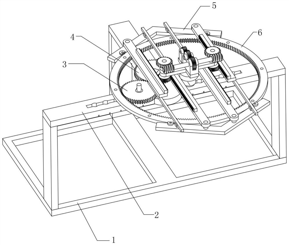
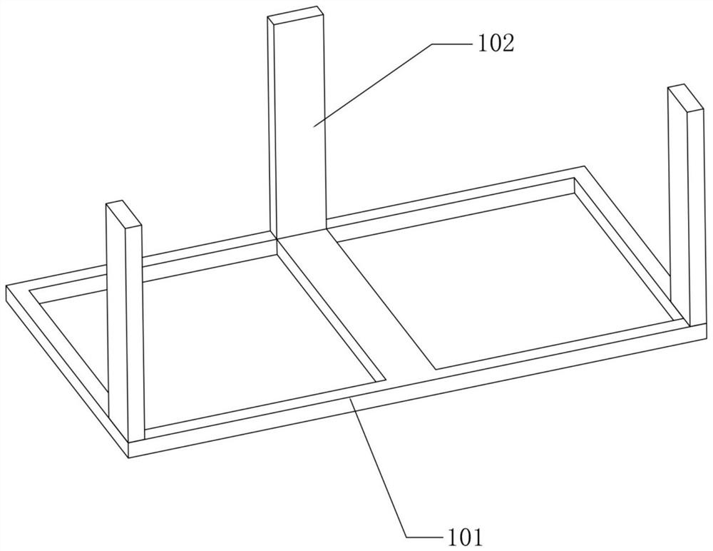
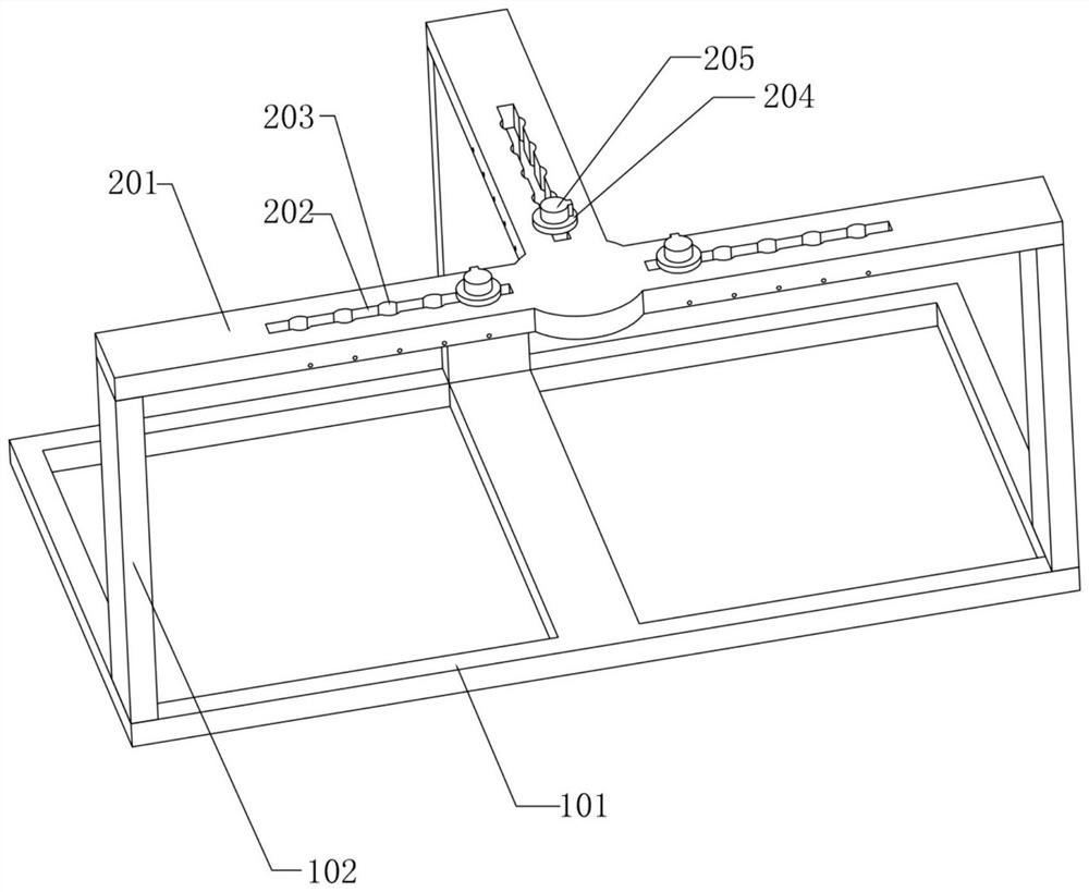
[0042] The present invention realizes the example of the multi-gap measurement test of spur gears as figure 1 , figure 2 , image 3 , Figure 4 , Figure 5 , Figure 6 and Figure 7 As shown, the test platform is fixed on the operation plane through the base frame assembly 1, and the platform bottom plate 201 in the main platform assembly 2 is connected to the top of the base frame assembly 1. The platform bottom plate 201 is a T-shaped structure, and each of the T-shaped structures All have conversion groove 202 on the main surface of each straight plate, all evenly be located in the array positioning hole 203 in every group of conversion groove 202, all can insert and install positioning socket 204 in every group of positioning hole 203, the top of every group of positioning socket 204 The gear plug 205 can be installed rotatably;
[0043] The outer wall of the T-shaped structure of the platform bottom plate 201 in the main platform assembly 2 is provided with locking...
Embodiment 2
[0054] The present invention realizes the example of the multi-gap measurement test of internal gear as figure 1 , figure 2 , image 3 , Figure 4 , Figure 5 , Figure 6 , Figure 8 , Figure 9 , Figure 10 and Figure 11 As shown, the internal gear insert 501 in the internal gear clamp assembly 5 can be installed in the gear plug 205 located at the right end of the T-shaped structure of the platform bottom plate 201, and the front and rear ends of the internal gear insert 501 are respectively provided with clamps 502 and opposite The joint clamp 503, and the joint clamp 502 and the opposite joint clamp 503 can be moved synchronously with the inner gear insert 501 as the center. The internal gear plug-in 501 is clamped in the array linkage wheel 504 as the center;
[0055] The two sets of main connecting rods 505 in the internal gear clamping assembly 5 are respectively symmetrically connected to the two ends of the connecting clamp 502, and the two sets of opposing...
PUM
 Abstract
Description
Claims
Application Information
 - Generate Ideas
- Intellectual Property
- Life Sciences
- Materials
- Tech Scout
- Unparalleled Data Quality
- Higher Quality Content
- 60% Fewer Hallucinations
Browse by: Latest US Patents, China's latest patents, Technical Efficacy Thesaurus, Application Domain, Technology Topic, Popular Technical Reports.
© 2025 PatSnap. All rights reserved.Legal|Privacy policy|Modern Slavery Act Transparency Statement|Sitemap|About US| Contact US: help@patsnap.com


