Single-rod bearing for high-speed rotation

A high-speed rotating, single-rod technology, used in the field of bearing lubrication, can solve the problems of inability to approach the bearing, affecting the service life of the bearing, and supplementing the bearing with lubricant, so as to avoid the risk of over-temperature, prolong the service life, and reduce the rotation resistance.

Active Publication Date:
View PDF9 Cites 0 Cited by
  • Summary
  • Abstract
  • Description
  • Claims
  • Application Information

AI Technical Summary

Problems solved by technology

[0003] The existing bearing lubrication cannot automatically and timely replenish the lubricant for the bearing, and manual lubrication is required on a regular basis, which is time-consuming and laborious, and the lubrication effect of the bearing is limited by the speed. When the rotor speed is low, due to the small centrifugal force, the axial After the oil is discharged, it can be sprayed smoothly into the bearing raceway to complete the bearing lubrication. However, when the rotor speed is high, due to the large centrifugal force, the oil will float away in the radial direction after the axial discharge, and cannot approach the bearing, resulting in insufficient lubrication of the high-speed bearing, resulting in The risk of bearing overheating seriously affects the service life of the bearing, and there are great safety hazards during the operation of the bearing

Method used


Image

  • Single-rod bearing for high-speed rotation
  • Single-rod bearing for high-speed rotation
  • Single-rod bearing for high-speed rotation

Examples


Embodiment 1

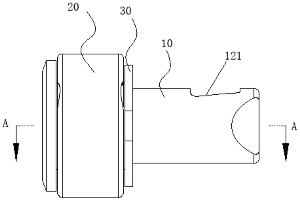
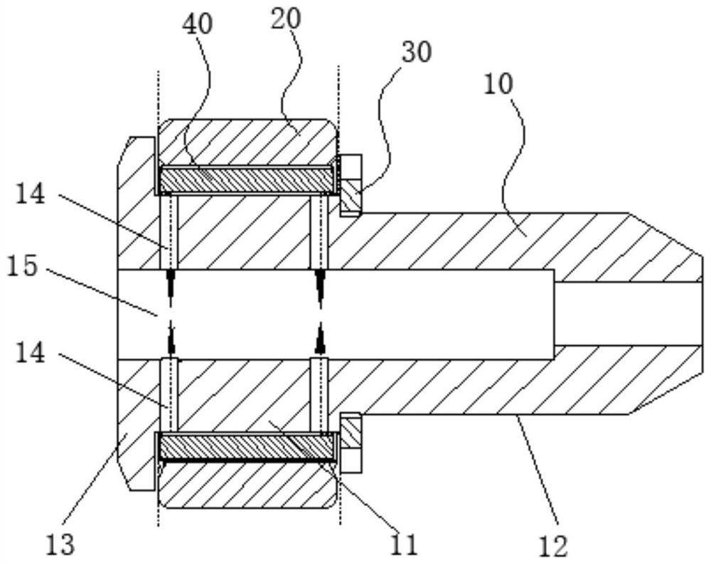
[0047] Such as Figure 1 to Figure 2 The shown single-rod bearing for high-speed rotation includes: a bearing rod 10, a bearing sleeve 20 and a bearing spacer 30. The bearing rod 10 is provided with a rolling step shaft 11 and a fixed step shaft 12 in sequence along the axial direction; 20 sets of bearing sleeves It is arranged on the rolling step shaft 11, and is located in the annular gap between the bearing sleeve 20 and the bearing rod 10, and a number of needle rollers 40 are evenly distributed along the circumferential direction, and two adjacent needle rollers 40 form an oil collection chamber 50 with the inner hole wall; The bearing spacer 30 is sleeved on the fixed step shaft 12 and interferes with the limit interface between the rolling step shaft 11 and the fixed step shaft 12; The limit flange 13 used to limit the axial movement of the bearing sleeve 20, the oil inlet grooves 21 arranged obliquely in the radial direction are provided on both end surfaces of the bea...

Embodiment 2

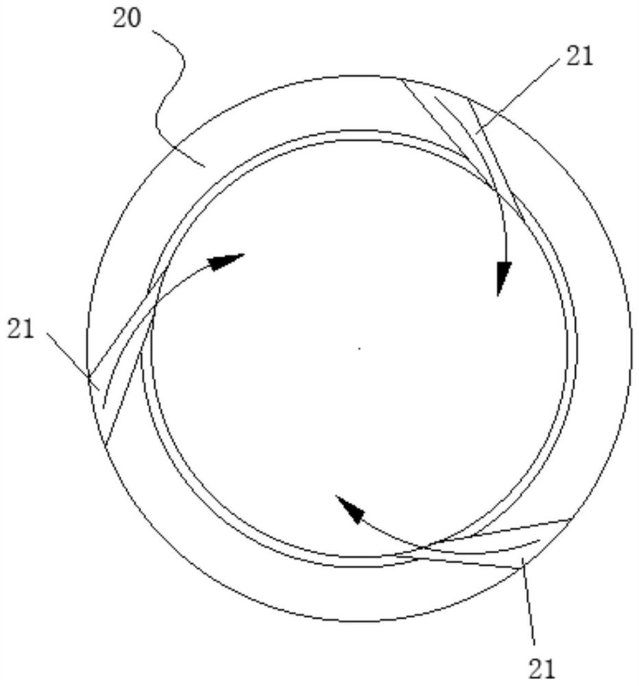
[0059] The difference between the present embodiment and the first embodiment is that the structure of the oil inlet groove 21 is different, and the rest of the structures are the same, and will not be repeated here. In this embodiment, as Figure 4 As shown, the oil inlet groove 21 is in the shape of an arc and penetrates radially from the outer edge to the inner hole; the depth of the oil inlet groove 21 gradually becomes deeper from the outer edge to the inner hole.

[0060] Specifically, on the basis of the circumferential inclination of the oil inlet groove 21, the depth of the bottom of the groove is changed, so that the inclination angle of the end facing the inner hole becomes larger, and the contact area between the lubricating oil and the needle roller 40 is increased, and the oil inlet groove 21 is evenly distributed along the circumferential direction. 3 pieces, when the bearing sleeve 20 rotates in the same direction as the oil inlet groove 21, the pressure on the ...


PUM


Abstract

The invention relates to the technical field of bearing lubrication, in particular to a single-rod bearing for high-speed rotation, which comprises a bearing rod, a bearing sleeve and a bearing gasket, the bearing sleeve is arranged on a rolling step shaft of the bearing rod, a plurality of roller pins are uniformly distributed and mounted in an annular gap along the circumferential direction, and two adjacent roller pins and an inner hole wall form an oil collecting cavity; the fixed step shaft is sleeved with the bearing gasket, the rolling step shaft is provided with a limiting flange which is matched with the bearing gasket and used for limiting the bearing sleeve to move in the axial direction, oil inlet grooves which are obliquely formed in the radial direction are formed in the end faces of the two sides of the bearing sleeve, the first oil hole in the bearing rod and the oil inlet grooves are communicated with the annular gap, and the first oil hole is communicated with the second oil hole. When the bearing rotates at a high speed, lubricating oil can quickly enter the annular gap through the pressure difference generated by rotation of the oil inlet groove and is quickly discharged through the first oil hole and the second oil hole, heat generated by the bearing is taken away in time while the roller pin is lubricated, the over-temperature risk of the bearing is avoided, and the service life of the bearing is prolonged.

Description

technical field [0001] The invention relates to the technical field of bearing lubrication, in particular to a single-rod bearing for high-speed rotation. Background technique [0002] Bearings are often used as guide rollers, valve stem rollers, cam rollers and pressure rollers for sliding, etc., and are mainly used in a variety of machinery, such as automatic machinery, special machinery, cam working devices, various handling systems, conveyors and machining centers. Knife device. [0003] The existing bearing lubrication cannot automatically and timely replenish the lubricant for the bearing, and manual lubrication is required on a regular basis, which is time-consuming and laborious, and the lubrication effect of the bearing is limited by the speed. When the rotor speed is low, due to the small centrifugal force, the axial After the oil is discharged, it can be sprayed smoothly into the bearing raceway to complete the bearing lubrication. However, when the rotor speed i...

Claims


Application Information

Patent Timeline
Patent Type & Authority Applications(China)
IPC IPC(8): F16C19/46F16C33/66F16C33/58F16C37/00
CPCF16C19/46F16C33/6659F16C33/58F16C37/007
Inventor 陈亮刘涛朱建国张海见
Why Eureka
Try Eureka