Automatic cutting device for building construction bricks
An automatic cutting device and construction technology, applied in the direction of work accessories, manufacturing tools, stone processing tools, etc., can solve the problems of polluted air, affecting the health, and the brick cutting device is not dustproof, so as to achieve the effect of protecting air quality
- Summary
- Abstract
- Description
- Claims
- Application Information
AI Technical Summary
Problems solved by technology
Method used
Image

Examples
specific Embodiment approach 1
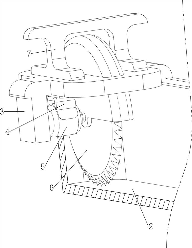
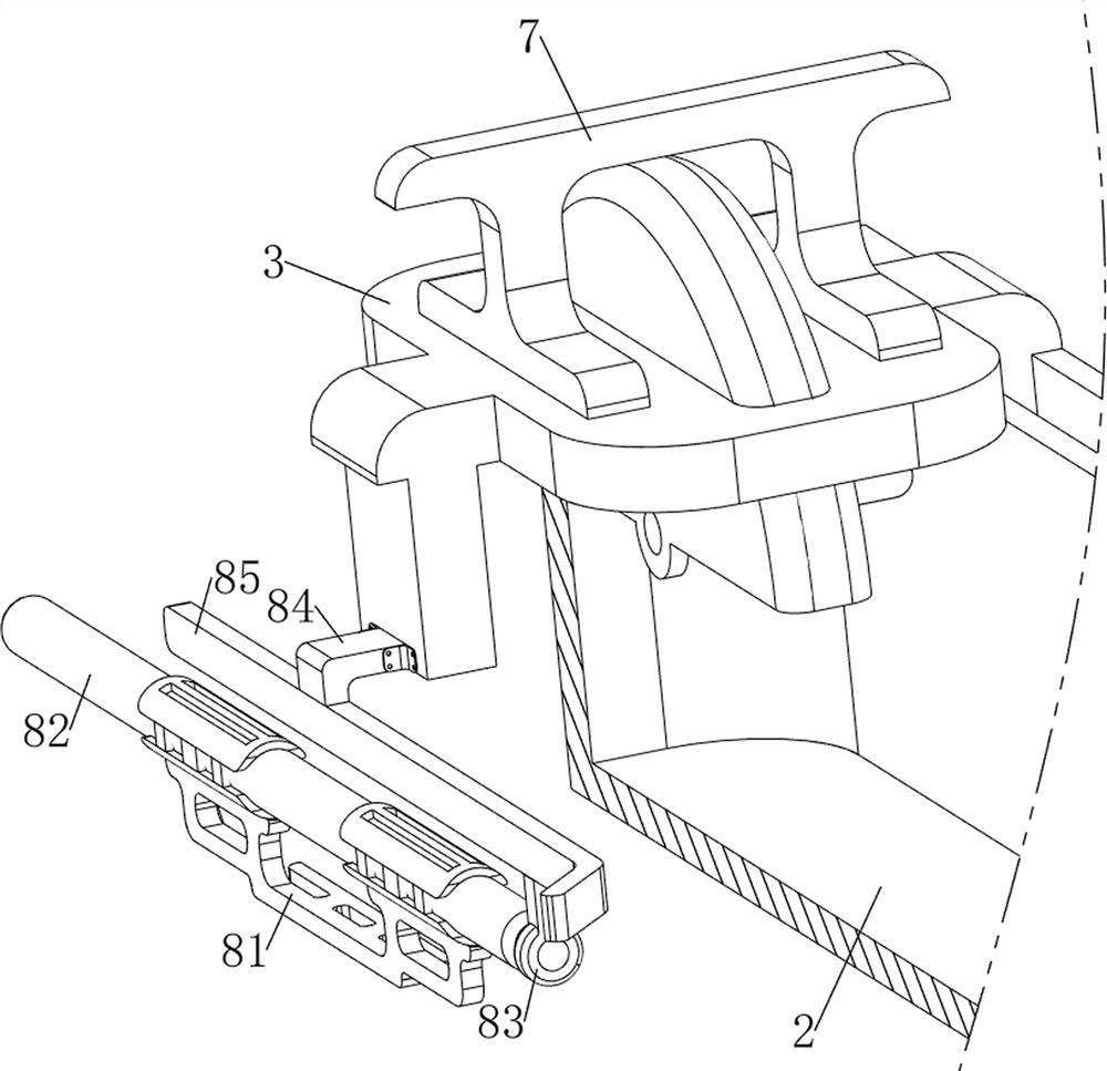
[0035] An automatic brick cutting device for building construction, please check Figure 1-9 , including a support frame 1, a shell 2, a connecting frame 3, a first fixed block 4, a motor 5, a blade 6, a first handle 7, a pushing mechanism 8, a protection mechanism 9 and a clamping mechanism 10, and the top of the support frame 1 is welded The shell 2 is connected, and the top of the shell 2 is slidably connected with the connecting frame 3, the top of the connecting frame 3 is connected with the first handle 7 by bolts, and the middle front side of the connecting frame 3 is connected with the first fixing block 4 by welding, the first fixing The bottom of the block 4 is equipped with a motor 5, the output shaft of the motor 5 rotatably runs through the connecting frame 3, and the middle part of the connecting frame 3 is rotatably connected with a blade 6, the blade 6 is positioned at the rear side of the motor 5, and the output shaft of the motor 5 is connected to the blade O...
specific Embodiment approach 2
[0040] On the basis of specific implementation mode 1, please check figure 1 , Figure 10 and Figure 11 , also includes a guide mechanism 11, the guide mechanism 11 includes a third fixed block 111, a second connecting rod 112, a second torsion spring 113, a guide plate 114 and a limit block 115, and the right side of the inner bottom of the shell 2 has an outlet Material hole, the bottom right side of the shell 2 is connected with two third fixing blocks 111 by welding, the two third fixing blocks 111 are symmetrically arranged front and back, and a second connecting rod 112 runs through between the two third fixing blocks 111 , the second connecting rod 112 is rotatably connected with a guide plate 114, the guide plate 114 is located inside the discharge hole, the second torsion spring 113 is connected between the guide plate 114 and the two third fixed blocks 111, and the two second The torsion springs 113 are all sleeved on the two second connecting rods 112, and the ri...
specific Embodiment approach 3
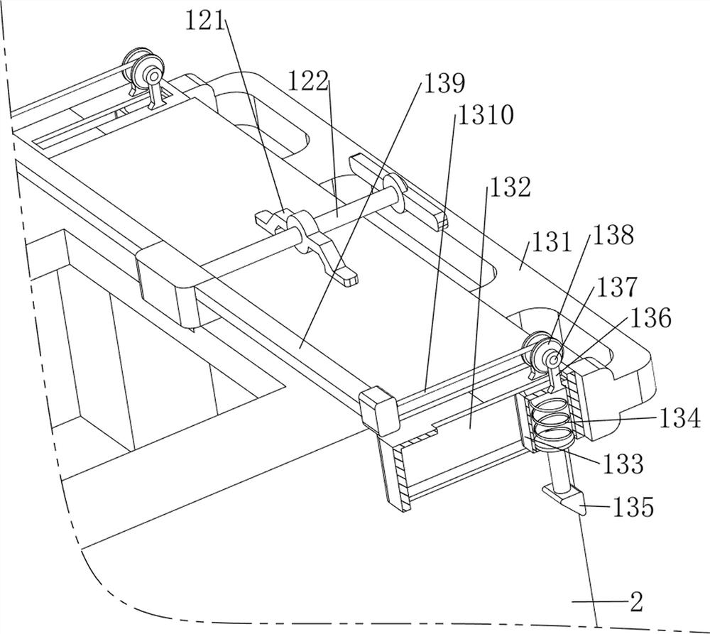
[0043] On the basis of the specific implementation mode 2, please check figure 1 , Figure 14 and Figure 15 , also includes a pulling mechanism 13, and the pulling mechanism 13 includes a third fixed frame 131, a guide frame 132, a slide block 133, a third spring 134, a third wedge-shaped rod 135, a fifth fixed block 136, a fourth connecting rod 137, Reel 138, the fifth connecting rod 139 and stay cord 1310, the right wall bottom of shell 2 is connected with the 3rd fixed mount 131 by welding, the front and rear two left sides of the 3rd fixed mount 131 are all connected with guide frame 132, two The guide frames 132 are symmetrical front and back, and the right sides of the bottoms of the two guide frames 132 are connected with two fifth fixed blocks 136 by welding, and the two fifth fixed blocks 136 on the same side are symmetrically arranged front and back, and the two fifth fixed blocks 136 on the same side are symmetrically arranged. The fourth connecting rod 137 runs ...
PUM
 Abstract
Description
Claims
Application Information
 - R&D
- Intellectual Property
- Life Sciences
- Materials
- Tech Scout
- Unparalleled Data Quality
- Higher Quality Content
- 60% Fewer Hallucinations
Browse by: Latest US Patents, China's latest patents, Technical Efficacy Thesaurus, Application Domain, Technology Topic, Popular Technical Reports.
© 2025 PatSnap. All rights reserved.Legal|Privacy policy|Modern Slavery Act Transparency Statement|Sitemap|About US| Contact US: help@patsnap.com